- 51 -
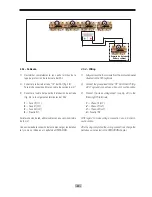
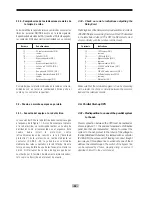
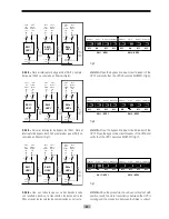
3.4.1.4.- Conexión del anillo de fibra óptica entre los
SAIs para la transferencia de datos.
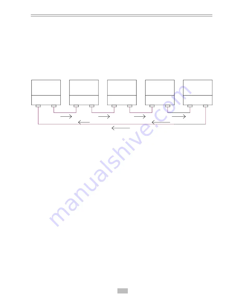
Para asegurar una correcta transferencia de datos entre los
SAIs del sistema paralelo, es necesario conectar los cables
que crean el anillo de comunicación entre ellos y a los puertos
de fibra óptica de la tarjeta de control CS0119 de cada uno.
Para una mayor seguridad se recomienda enfundarlos para
evitar fallos o deterioros.
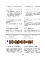
3.4.1.5.- Interface a relés.
Se recomiendan utilizar alarmas visuales o sonoras controla-
das directamente por el interface de relés de la tarjeta CS0118
(relés) situado en la parte trasera del SAI. El conexionado se
realizará según el manual de usuario. También es posible
visualizar el estado del sistema a través de un adaptador
SNMP mediante el software de monitorización de SALICRU.
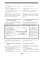
3.4.2.- Comprobación de las conexiones eléctricas
del SAI.
La secuencia de comprobación indicada en este punto debe
ser llevada a cabo con los cables de comunicación del para-
lelo (fibra óptica) desconectados, así como también los ca-
bles de las baterías.
2.1.-
Con el SAI parado (todos los interruptores en posición
OFF) comprobar que la secuencia de fase es la correcta.
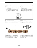
3.4.1.4.- Optical connection between the UPS for
transfer data.
To ensure data transfer between UPS of the systems connect
optical fiber on control logic board CS0119 creating a communi-
cation loop as shown in the following picture, for a better
safety is advisable to cover optical fiber to avoid their damaging.
3..4.1.5.- Remote signallings.
It is advised a visual or sonorous visualization of the alarm
from the system that it can be made wiring the free contact
on the communication board CS0118(relay) situated on the
rear of all the UPS on the sinoptic panel like described on the
user manual,it is possible to visualize all the state of the
system through the SNMP interface by SALICRU software.
3.4.2.- Verification of the UPS electrical connection.
The sequence of the procedures listed in this paragraph must
be carried out having the optic fibres for the parallel installa-
tion not connected. Also the batteries must be disconnected.
2.1.-
Having the UPS unactive (all the circuit breakers in
OFF position) check the phase sequence and that the pha-
se rotation is right.
UPS 1
UPS 2
UPS 3
UPS 4
UPS N
(N MAX =8)
AT THE SECOND INTERRUPTION THE
OPTICAL FIBER COMMUNICATION
RING
RX2
RX2
RX2
RX2
RX2
TRX2
TRX2
TRX2
TRX2
TRX2
CS0119
CS0119
CS0119
CS0119
CS0119
Anillo de comunicación de fibra óptica /
Optical Fiber Communication Ring
A la primera interrupción del anillo el
sistema sobrevive /
At the first
interruption the system survives
A la segunda interrupción del anillo el
sistema pasa a Bypass /
At the second
interruption the system switches on Bypass
Summary of Contents for SLC ELITE MAX Series
Page 2: ...2...
Page 79: ...79...
Page 80: ...salicru com 08460 Palautordera Tel 34 93 848 24 00 sat salicru com...

