- 22 -
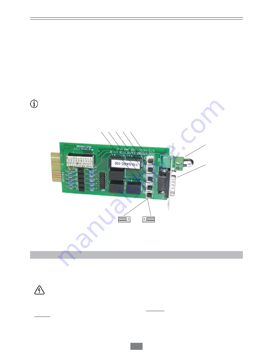
• By default the 5-dry contacts AS/400 is supplied with the contacts normally closed (NC). When the alarm is activated, the dry
contact changes its status being opened. Selectively this condition can be changed to normally opened individually for each
dry contact, by modifying the position of the jumpers of the card or electronic unit (see table 3 and figure 5).
• As this card has its own SUB-D9 connector, a second REPO
(C15)
connector with the same function of the one in the
equipment and described in the section 7.8 is included.
• Once the physical connection has been made with the cable between the
UPS
and the computer, and the optional software
has been installed, the operation system will be intelligent, giving the full protection capacity to the supplied critical loads
when the complete installation is working.
The connection of the interface between the
UPS
and the computer is not implicit to the operating of both units.
7.10.1.2.- SNMP/WEB card or electronic unit.
•
The communication lines (interface) constitute a safety circuit of very low voltage. To preserve this quality, they should
be installed separated from other lines with dangerous voltages (like distribution lines of energy).
• Through the SNMP/WEB electronic card, the
UPS
can be both supervised at distance either a Web Browser «Http» or
managed through an optional monitoring software (control of the mains, order of closing of files,...). Insert the CD of the
optional software in the computer and read carefully the related instructions to the connection and operation of itself.
Fig. 5. Card or electronic unit, 5-dry contact AS/400 optional.
REPO connector.
SUB-D9 connector,
relay interface.
JP1
JP2
JP3
JP4
JP5
Bridge between pins NC, by default the 5-dry con-
tacts are supplied in this position. The interface gives
the alarm contacts normally closed (dry contacts),
in the SUB-D9 connector of the own card or elec-
tronic unit
Bridge between pins NO. The interface gives the
alarm contacts normally opened (dry contacts), in
the SUB-D9 connector of the own card or elec-
tronic unit.
NO
NC
Summary of Contents for SLC Link Series
Page 1: ...EK708A01 SLC LINK Service Manual...
Page 64: ...63...
Page 65: ...08460 Palautordera Tel 34 93 848 24 00 sat salicru com salicru com...
Page 99: ...34...
Page 138: ...73...
Page 139: ...74...
Page 140: ...75...
Page 141: ...08460 Palautordera Tel 34 93 848 24 00 sat salicru com salicru com...


