17
SALICRU
Before downloading the equipment from the pallet, the
stabilizer supports have to be removed (see figure 8), oth-
erwise they will make difficult the process and they will
be bent when impacting with the wooden ramp, making
damages and the own case or cabinet structure of the
equipment.
Put the ramp as figure 7 and download the equipment
from the pallet.
4.2.4. Transport to location.
•
All equipments have four casters (two of them with brake),
so it is easy to move it till the installation location once it is
unpacked.
Nevertheless, if the reception area is far from the installation
place, it is recommended to move the UPS with a forklift or a
suitable transport medium keeping in mind the distance be-
tween both points.
If the distance is too long, it is better to move the equipment
packed till the installation place and unpack it there.
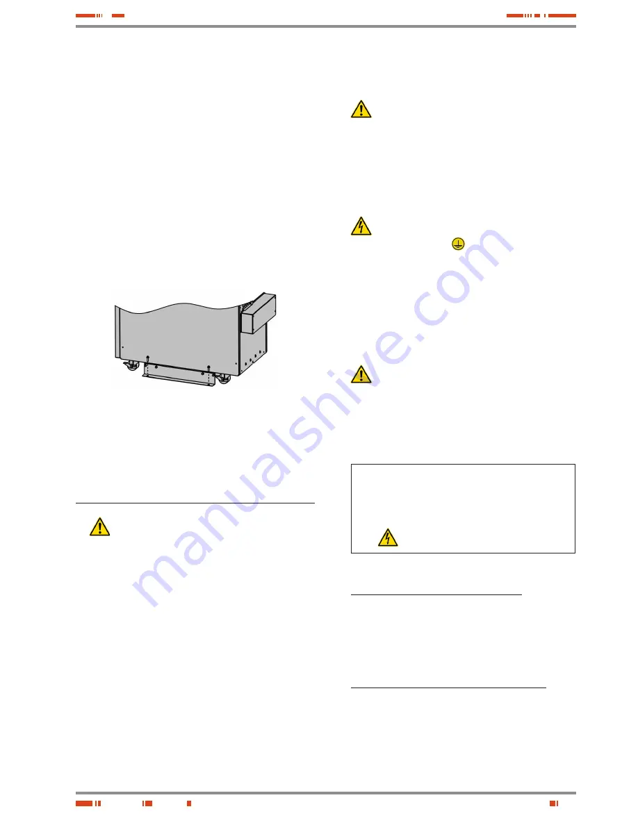
Fig. 9.
•
If it is appropriated and as a preventive measure, the stabi-
lizing supports can be reassembled (see Figure 8), to avoid
the dump of the device. Optionally the equipment can be
locked, by fixing it to the floor through the holes provided in
the same support (see figure 9).
4.3. Connection.
•
Cross cable section used in the power supply of the
equipment and loads to feed, will be sized according
to the nominal current stated in the nameplate sticked on the
equipment, by respecting the Low Voltage Electrotechnical
Regulations or norms of the corresponding country.
•
Installation will have the suitable input protections sized to
the current of the equipment and stated in the nameplate of
the equipment (residual current devices type B and circuit
breaker with C characteristic or any other equivalent one).
For equipment with three phase input, which are connected
to a power distribution system type IT, the protection will be
four poles in order to break the three phases and neutral in the
same manoeuvring.
Overload conditions are considered as a nonpermanent an
exceptional operating mode, so these currents will not be
kept in mind when sizing the protections.
•
Output protection will be done with a circuit breaker of C char-
acteristic or any other equivalent one.
•
To make the power, control connections or insert the option
cards, etc..., it is needed to remove the screws that fix each
cover and the own covers.
When finalising the corresponding tasks the cover/s and their
fixing screws will be fitted back.
•
It is recommended to use pointed terminals in all ends of the
cables connected to the power blocks (input, output and by-
pass).
•
Check the correct torque in the screws of the power blocks.
•
In installations with only one UPS, the "Jumper" (cable
as bridge mode) connected from factory between the
terminals
JP1
and
JP2
has to be kept as it is.
For equipments connected in a parallel system, this "Jumper"
has to be removed.
Act according to the installation or otherwise the UPS or par-
allel system will not work.
4.3.1. Connection of input power block.
•
As this is a device with class I protection against elec-
tric shocks, it is essential to install a protective earth
conductor (connect earth(
)
). Connect the conductor to
the terminal, before connecting the power supply to the input
power block.
•
In accordance with safety standard EN-IEC 62040-1, the in-
stallation has to be provided with a «Backfeed protection»
system, as for example a contactor, which will prevent the
appearance of voltage or dangerous energy at the input
mains during a mains fault (see figure 10 and respect the
circuit diagram of the particular «Backfeed protection» for
the equipment with single phase input (
TWIN PRO
) or three
phase input (
TWIN/3 PRO
up to 10 kVA)).
There can be no derivation in the line that goes from
the «Backfeed protection» to the UPS, as the safety
standard would be infringed.
•
Warning labels should be placed on all primary power
switches installed in places away from the device to alert the
electrical maintenance personnel of the presence of a UPS
in the circuit.
The label will bear the following or an equivalent text:
Before working on this circuit.
•
Isolate Uninterruptible Power System (UPS).
•
Then check for Hazardous Voltage between all
terminals including the protective earth.
Risk of Voltage Backfeed from UPS.
•
Connect the input cables to the respective power block de-
pending on the configuration of the equipment (see figure 11).
Connection in a single phase input (TWIN)
:
Connect the power supply cables to input power blocks
R (L)
and
N
,
by respecting the rotation of phase and neutral
stated in the labelling of the equipment and in this manual.
If this rotation is not respected there could be fault/s and/or
anomalies.
When discrepancies exist between the labelling and the in-
structions of this manual, the labelling will always prevail.
Connection in a three phase input (TWIN/3 PRO)
:
The described connection instructions are valid for all
TWIN/3 PRO
equipments, being the only difference the
connection of the «Backfeed protection», which depending
on the power it will be connected in the three phase
input (
TWIN/3 PRO
up to 10 kVA) or in the bypass line
(
TWIN/3 PRO
> 10 kVA).
Summary of Contents for SLC TWIN PRO Series
Page 2: ......
Page 43: ...43 SALICRU...


