21
SALICRU
4.3.7. Connection in parallel.
4.3.7.1. Introduction to the redundancy.
N+X is usually the most reliable power structure. N means the
minimum quantity of equipments that the total load needs; X
means the quantity of redundant equipments, so it means, the
quantity of faulty UPSs that the system can allow at the same
time. As higher is X, the highest will be the reliability of the
system. For those cases where the reliability is the most impor-
tant point, N+X will be the optimal mode.
Up to 4 equipments can be connected in parallel to set a share
and redundant output in power.
4.3.7.2. Installation and parallel operating.
•
Communication line (COM) is a very low voltage circuit
of safety. To preserve the quality, it has to be installed
separate from other lines that have dangerous voltages (energy
distribution line).
•
Parallel connection bus
. Use the bundle with 25 signal ca-
bles with mesh and DB25 connectors in the ends to joint up
to 4 equipments as maximum. Each bundle has a male and
female connector in the ends, which have to be connected in
the correlative equipments. It is essential to close the loop of
the parallel bus.
The length of the parallel cable has 3 metres and it can't be
extended under any other concept due to the risk of interfer-
ences and communication failures that it could cause.
•
In those installations with only one UPS, the “Jumper”
(cable as bridge mode) connected from factory be-
tween the terminals
JP1
and
JP2
has to be kept in this place.
For equipments connected in a parallel system, this “Jumper”
has to be removed.
Proceed according to your installation or otherwise the UPS
or parallel system will not work.
•
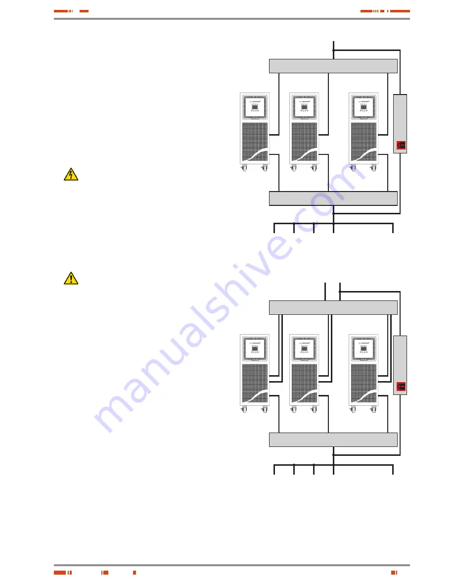
The installation of the parallel systems, has to be provided
by a switchgear panel with individual protections for input,
output, static bypass (this last one for
TWIN/3 PRO
> 10 kVA
models only), also a manual bypass with mechanical lock,
see figures 12 and 13.
This switchgear panel allows isolating only one equipment from
the system, against any failure and feed the loads with the rest
of equipments during the preventive maintenance or its fixing. In
the same way, it allows removing an equipment in parallel and
replace it or put it in parallel again once it is fixed, but without
breaking the power supply to the loads.
Under request a manual Bypass panel can be supplied for a
single equipment or particular system.
•
Regarding the protection panel, it is better to size it for future
foreseen upgrading. This way, both the installation of any new
UPS in the parallel system is easier, and the risks due to elec-
trical discharge are minimized because the low voltage panel
is manoeuvred for those cases that it is not possible to shut-
down the loads.
•
Respect the connection procedure for input and bypass
(
TWIN/3 PRO
> 10 kVA) described in the previous sections
of this chapter.
•
Respect the established procedure to make the connection of the
battery modules for those equipments with extended back up time,
which has been described in the previous sections of this chapter.
•
Respect the established procedure to make the connection of
the output (loads), which has been described in the previous
sections of this chapter.
• • •
Input circuit breakers
Output circuit breakers
M
anu
al
B
yp
as
s
UPS nr 1
UPS nr 2
UPS nr
"N"
Input
To loads
• • •
Fig. 12.
Parallel installation of TWIN PRO and TWIN/3 PRO UPSs up to 10
kVA, with protection and manual bypass panel.
• • •
Input and bypass circuit breakers
Output circuit breakers
M
anu
al
B
yp
as
s
UPS nr 1
UPS nr 2
UPS nr
"N"
Input
To loads
• • •
Bypass line
Fig. 13.
Parallel installation of TWIN/3 PRO series > 10 kVA, with
manual bypass and protection panel.
•
Respect the established procedure to make the connection
of the output and batteries of the equipment, which has been
described in the previous sections of this chapter.
Summary of Contents for SLC TWIN PRO Series
Page 2: ......
Page 43: ...43 SALICRU...


