16
SALICRU
5.2.3. Connection to B1 external batteries (backup extension).
•
Failure to comply with the instructions in this sec-
tion and the EK266*08 safety instructions carries a
high risk of electric shock and even death.
•
All standard UPSs incorporate the batteries in the same box as
the device, except the B1 models. Battery protection is by means
of internal fuses and is not accessible to the user.
The accumulator modules also have internal battery protections
by means of fuses that are not accessible to the user.
•
NECESSARY ADJUSTMENTS WHEN ADDING BAT-
TERY MODULES TO B1 MODELS.
B1 models have factory default settings for connection to a
single battery module.
Whether battery modules are added to an already available de-
vice or if the acquired device has more than one module, it is
necessary to change the parameter "12" to the corresponding
value.
Section 7.4.2.1 of this document indicates the steps to follow to
adjust this setting and that of the load current.
•
IMPORTANT FOR SAFETY: If you install batteries on your
own, you must provide the battery pack with bipolar
magnetothermal protection or sectional fuses of the caliber
indicated in Tab. 2.
Models
Batteries
(U
element
x No.) =
U
rated
/ U
float
Protection features
Voltage
DC (V)
Current
(A)
SLC-1000- TWIN PRO2 A B1
(12 V x 3 ) =
36 V / 40.95 V
125
40
SLC-2000- TWIN PRO2 A B1
(12 V x 4 ) =
48 V / 54.6 V
63
SLC-3000- TWIN PRO2 A B1
(12 V x 6 ) =
72 V / 81.9 V
Tab. 2.
Protection features between UPS and battery module.
•
Before starting the connection process between
battery module or modules and device, check that
the device and loads are set to ‘Off.’
•
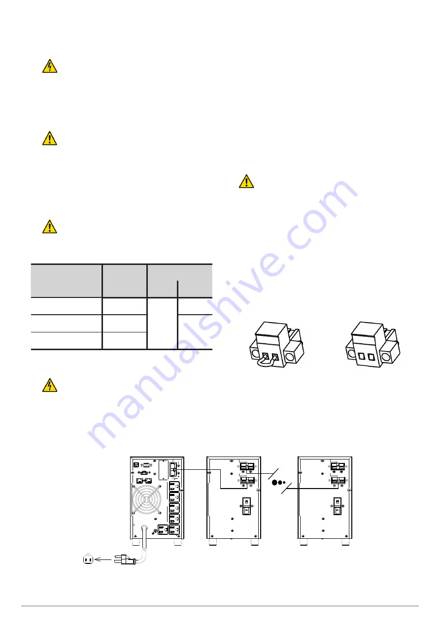
The connection of external batteries to the device is carried out
by means of a polarised connector on B1 models.
•
To connect the device to the battery module, use the hose sup-
plied with the latter and connect it between both units using the
connectors.
When more than one battery module is supplied for the same
device, the connection between modules should be made
through the hose supplied with the second battery module.
Fig. 11 shows an example of the connection of an SLC-TWIN
PRO2 A B1 with ‘N’ battery modules. Except for the rear view of
the model, it is applicable to the entire range indicated in this
manual. Connect the available modules according to each case.
•
If for any reason the user manufactures the battery connection
hose, the following cable colour conventions must be observed:
red for positive, black for negative, as well as the connection
correlation (+ with + and – with –).
•
Each battery module is independent for each device.
It is
strictly forbidden to connect two devices to the
same battery module
.
5.2.4. Terminals for EPO (Emergency Power Off).
•
All of the UPSs have two terminals for the installation of an
external emergency power off [EPO] output button.
•
The device is dispatched from the factory with its EPO circuit set
to closed [NC] by default. This means that the UPS will cut the
output power supply, emergency power off, when the circuit is
opened:
Either by removing the female connector from the socket
where it is inserted. This connector has a cable connected
as a jumper that closes the circuit [Fig. A],
Fig. A
Fig. B
or by pressing the button installed external to the device
belonging to the user. The connection on the button must
be in the normally closed contact in order to open the circuit
when activated.
UPS
Module 1
Module ‘n’
OUTPUT
USB
RS232
INTELLIGENT SLOT
USB
RS232
INTELLIGENT SLOT
INPUT
20A max.
PROGRAMMABLE
OUTLETS(P1)
10A max.
OUTPUT
INPUT
2K
3K
EPO
IN
OUT
NETWORK/FAX/MODEM
EPO
T
U
O
N
I
NETWORK/FAX/MODEM
R20160615-001A
Rear panel view for Galleon One
1-3K LV and HV
IN
TE
LL
IG
E
N
T
S
LO
T
EPO
RS232
T
U
O
N
I
USB
INPUT
NETWORK/FAX/MODEM
1K/1.5K
PROGRAMMABLE
OUTLETS(P1)
LV
PROGRAMMABLE OUTLETS(P1)
10A max.
O
U
TP
U
T
TOWER 12BATTERY
TOWER 18BATTERY
Rack 12BATTERY
TOWER 4BATTERY
TOWER 8BATTERY
TOWER 6BATTERY
TOWER 16BATTERY
BATTERY BREAKER
Max, 50A
BATTERY BREAKER
Max, 50A
BATTERY BREAKER
Max, 50A
BATTERY BREAKER
Max, 50A
BATTERY BREAKER
Max, 50A
BATTERY BREAKER
Max, 50A
BATTERY BREAKER
Max, 50A
TOWER 12BATTERY
TOWER 18BATTERY
Rack 12BATTERY
TOWER 4BATTERY
TOWER 8BATTERY
TOWER 6BATTERY
TOWER 16BATTERY
BATTERY BREAKER
Max, 50A
BATTERY BREAKER
Max, 50A
BATTERY BREAKER
Max, 50A
BATTERY BREAKER
Max, 50A
BATTERY BREAKER
Max, 50A
BATTERY BREAKER
Max, 50A
BATTERY BREAKER
Max, 50A
Fig. 5.
Connection between device and ‘n’ battery modules.


