17
•
It is recommended to use cable-end sleeves on all of the
ends of the cables connected to the terminals, especially
those with power (input, output and batteries).
•
Check that the terminal screws are correctly tightened.
5.2. CONNECTIONS.
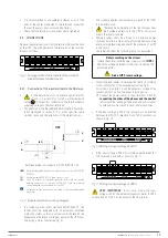
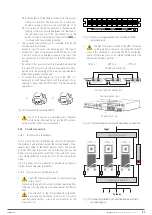
Remove the protective cover from the terminal block at the back
of the UPS. The arrangement of the terminals of the terminal
block is as follows:
A
N
0
208V
240V
Non-In
L
N
L2
OUTPUT
ISO TAP SELECTION
INPUT
Fig. 8.
Arrangement of the terminals of the terminal
block (Remove terminal cover)
5.2.1. Connection of the input terminals to the AC mains.
•
As the device has class I protection against electric
shock, it is essential to install a protective earth
cable [
]. Connect this conductor to the terminal before
supplying voltage to the input terminals.
•
Pay attention to the ‘Recommended installation’ documen-
tation mentioned in section 5.1.5.4., which specifies cable
sections, sizes and characteristics of the protections, etc.
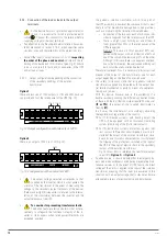
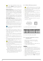
Backfeed protection connection for TWIN PRO2 T UL.
(BP)
Automatic backfeed protection system external to the UPS (EN-IEC
62040-1).
(1)
General purpose 600V AC / 1A type F fuse or fuses.
(2)
400V AC bipolar or tetrapolar contactor with minimum spacing
between contacts of 1.4 mm and 230V AC coil with the minimum
current indicated on the nameplate of the UPS.
For parallel systems, each device must have its own separate backfeed
protection.
R
N
(2)
Input
Output
UPS
U
N
(1)
(BP)
Fig. 9.
Backfeed protection wiring diagram.
•
In accordance with safety standard EN-IEC 62040-1, the
facility must be equipped with an automatic backfeed
protection system, such as a contactor, which prevents the
appearance of hazardous voltage or power on the UPS input
line during a mains failure [see Fig. 9].
The standard applies indiscriminately to each of the UPSs
in a parallel system.
•
There can be no derivation of the line that goes from
the backfeed protection to the UPS, as this would
breach the safety standard.
•
Warning labels shall be affixed to all primary power
switches installed in areas remote from the device to alert
electrical maintenance personnel of the presence of a UPS
in the circuit.
The label shall bear the following text or an equivalent:
Before working on the circuit.
•
Isolate the uninterruptible power supply system
(UPS)
.
•
Check the voltage between all terminals, including the
protective earth.
Risk of UPS return voltage.
•
Connect the input cables to the respective terminals according
to the configuration of the available device [see Fig. 9].
For systems in parallel, it will be necessary to repeat the
connections that go from the panel to each device.
Connect the power cables to input terminals R and N,
respecting the order of the phases and the neutral
indicated on the labelling of the device and in this manual.
Failure to do so may result in faults and/or anomalies.
•
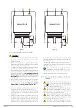
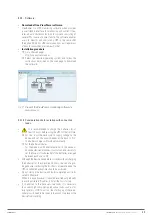
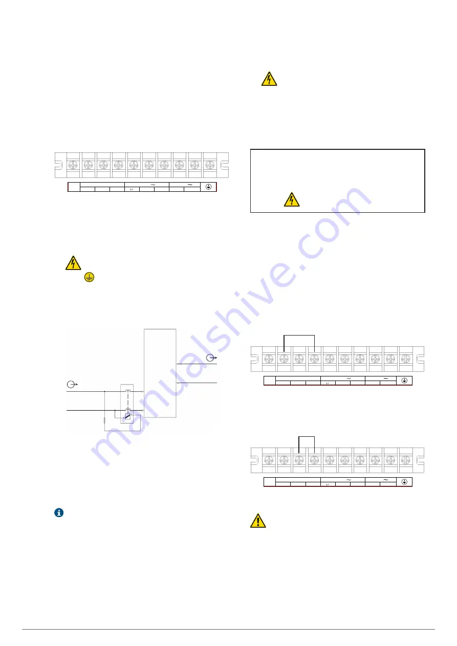
If the input voltage is 240 V, the jumper must be inserted
between the ISO TAP selection 0 and 240 V terminals, as
shown in Fig. 10:
A
N
0
208V
240V
Non-In
L
N
L2
OUTPUT
ISO TAP SELECTION
INPUT
Fig. 10.
Wiring for input voltage of 240 V.
•
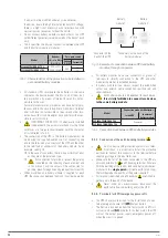
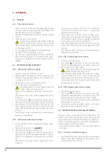
If the input voltage is 208 V, install the jumper between ISO
TAP selection 0 and 208, as shown in Fig. 11:
A
N
0
208V
240V
Non-In
L
N
L2
OUTPUT
ISO TAP SELECTION
INPUT
Fig. 11.
Wiring for input voltage of 208 V.
VERY IMPORTANT
: In this case, where the input
voltage is 208 V, the output voltage must be set to 208 V
to have 240 V or 120 V at the output of the transformer.
SLC TWIN PRO2 T
UL
UNINTERRUPTIBLE POWER SUPPLIES (UPS)
USER MANUAL


