18
SALICRU
5.2.2. Connection of the load or loads to the output
terminals.
•
As the device has class I protection against electric
shock, it is essential to install a protective earth
cable [
]. Connect this conductor to the terminal before
supplying voltage to the input terminals.
•
Pay attention to the ‘Recommended installation’ documen-
tation mentioned in section 5.1.5.4., which specifies cable
sections, sizes and characteristics of the protections, etc.
•
Connect the loads to output terminals L1, N, L2,
respecting
the order of the phase and neutral
indicated in the la-
belling of the device and in this manual [see Fig. 8]. Failure
to do so may result in faults and/or anomalies in the UPS
and/or load or loads.
5.2.2.1. Output configurations depending on the connection
of the secondary windings of the isolation
transformer.
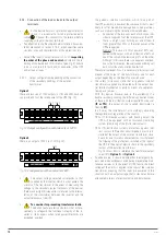
Option 1
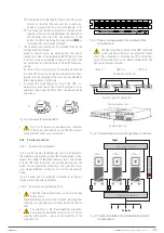
There are two sets of 120V outputs in L1-N and L2-N. Each set
can provide 50% of the rated power of the UPS [Fig. 12].
A
N
0
208V
240V
Non-In
L
N
L2
OUTPUT
ISO TAP SELECTION
INPUT
120 V 120 V
Fig. 12.
Output configuration with two sets of 120 V.
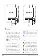
Option 2
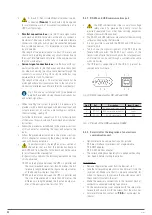
There is an output of 240 V in L1-L2 [Fig. 13].
A
N
0
208V
240V
Non-In
L
N
L2
OUTPUT
ISO TAP SELECTION
INPUT
240 V
Fig. 13.
Configuration with an output of 240 V.
•
The output voltage selected corresponds to that
supplied by the inverter, which is what powers the
primary of the transformer. In the event of measuring the
voltage in the secondary (output terminals of the device),
there may be slight discrepancies in relation to the interca-
lation of the transformer between the inverter and the
output terminals of the UPS.
•
To consider for preventing transformer faults.
The device features alerts and alarms that act pre-
ventively to safeguard the functional integrity of the in-
verter or static bypass when rated power thresholds are
exceeded, overload.
The galvanic isolation transformer, which forms part of
the UPS assembly, is however the component that is most
likely to suffer irreversible damage due to bad practices,
such as not observing the limitation indicated below:
–
Connection of the two coils: each of which can indi-
vidually supply 50% of the total power of the UPS.
–
There is a high risk of burning out one of them if
loads greater than 50% of the rated power of the
UPS are applied.
Example: The case of a total power of 80% con-
nected to the output, with a distribution of 65% on
one of the coils and the remaining 15% on the other.
Although in this case there is no apparent overload,
due to the distribution, the overloaded winding will
burn out without any overload detection.
Therefore, to prevent risks, it is necessary to install a circuit
breaker at the output of the transformer or one for each
output, depending on the type of connection used.
•
The safety instructions state that all galvanic isolation
transformers supplied are delivered with the output neu-
tral terminal connected to earth by means of a cable func-
tioning as a jumper.
With this device, however, due to the availability of a
double secondary winding, the different connection modes
of these and the distribution system required by the user
(IT or TN)
, the output of the supplied transformer is
floating
(IT)
.
In all cases, the installer must act accordingly, observing
the regulations or legislation of the country.
For IT distribution systems, with floating output, the
UPS will be equipped with an insulation monitoring
system (monitoring of the first insulation fault).
For TN distribution systems, protections against indi-
rect contact (differential circuit breaker) must be in-
stalled at the output of the isolation transformer, since,
due to its own insulation characteristics, it will prevent
the tripping of the protections installed at the input of
the UPS in the event of electric shock in the secondary
(output of the isolation transformer).
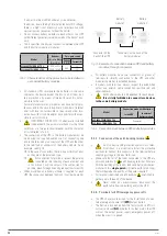
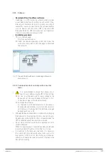
Fig. 14 shows how to reference the transformer output
to earth for
Option 1
and
Option 2
.
•
As added value, it should be noted that in emergency By-
pass mode (manual Bypass), used during preventative main-
tenance services or in the event of UPS failure, the direct
voltage of the mains is applied to the input of the isolation
transformer, meaning that the loads are powered in this
situation with an output voltage that is cleaner and more
attenuated in terms of electrical noise and disturbances.


