8
SALICRU
4. PRESENTATION.
4.1. VIEWS.
4.1.1. Views of the device.
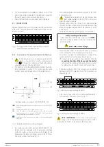
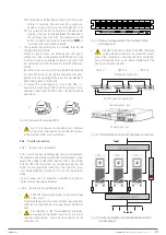
Figures 1 and 2 show illustrations of the devices in their single
enclosure format for both powers. However, because the
product is constantly evolving, discrepancies or slight contra-
dictions may arise. If in any doubt, the labelling on the device
itself will always prevail.
The nameplate of the device shows all of the values
relating to its main properties and characteristics. Act
accordingly for its installation.
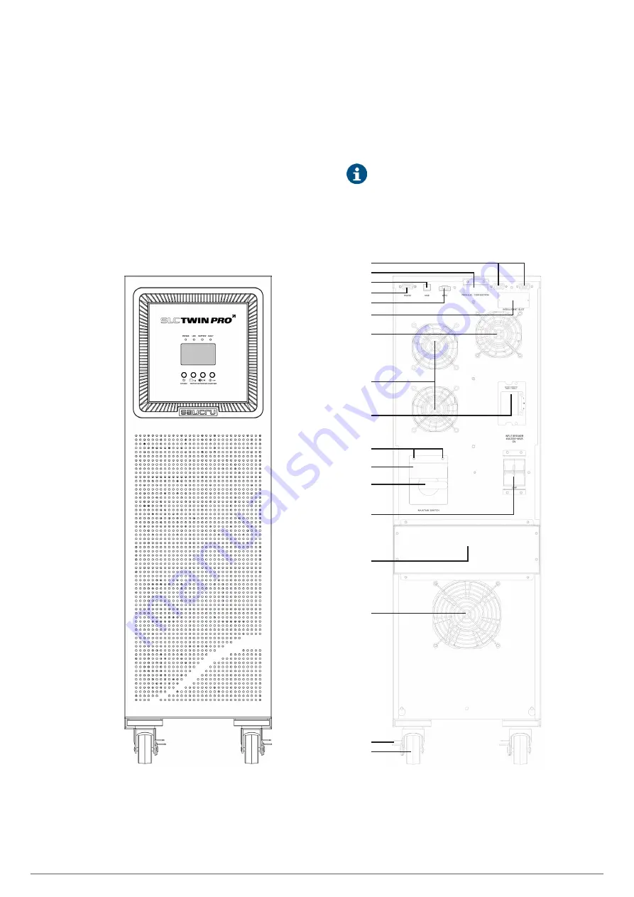
Parallel port
Current signal bus port
USB port
RS-232 port
EPO connector
Smart slot cover
Charger fan
Power stage fans
External battery
connector cover
MB block screws
MB block
Manual bypass -MB-
Input protection
Connection terminals cover
Input/output terminals,
see Fig. 9
Isolation transformer fan
Wheel brake
Rotating wheels
Fig. 1.
Front and rear view of 6 and 10 kVA models.


