background image

21

This type of output power distribution will ensure that a 

fault in any of the machines connected to the device that 

causes a short circuit does not affect more than the line 

that is faulty. 

The remaining connected loads will have continuity as-

sured due to the tripping of the protection only in the line 

affected by the short circuit.

5.2.3.  Connection to external batteries (backup extension).


Failure to comply with the instructions in this 

section and Safety Instructions EK266*08 carries 

a high risk of electric shock and even death.


The battery protection of the device and of any accumulator 

module is always by means of internal fuses that are not 

accessible to the user.


IMPORTANT FOR SAFETY

: If batteries are installed 

independently, the accumulator group must be fitted 

with a bipolar circuit breaker or disconnect fuse of the size 

indicated in Tab. 2.

Model

Rated battery 

voltage

Minimum values,  

fast type fuses 

DC voltage 

(V)

Current  

(A)

SLC-6000-TWIN RT2 T UL

(12V x 16) = 192V

400

32

SLC-10000-TWIN RT2 T UL

50

Tab. 2. 

Protection features between device and battery 

module.


Before starting the connection process between 

battery module or modules and device, check that 

the device and loads are ‘Off’.

Also, when the batteries are installed by the user indepen-

dently, the protection fuse or isolator must be deactivated.


Connection of the battery module to the device is made by 

means of a cable featuring polarised connectors at both 

ends, which is supplied with the first one. Two connectors are 

available for this purpose on the device and battery module.

Similarly, the battery modules feature two connectors that 

allow the linking of modules in parallel.


Each battery module is independent for each device. 

Two devices must not be connected to the 

same battery module

.

Likewise, in parallel systems, with each device connected 

to its battery module or modules, they should be considered 

as single devices that are independent of each other.


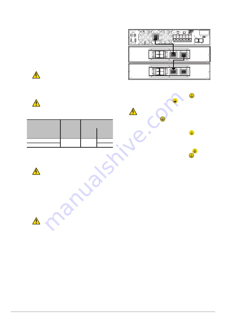
Fig. 21 shows the connection of a 10kVA device in a rack 

arrangement with two battery modules. For a larger 

number, proceed in a manner similar to those shown in the 

illustration.

Fig. 21. 

Connection to battery modules.

5.2.4.  Connection of the input earth terminal 

(

)

 and the 

earth connection terminal 

(

)

.


As the device has Class I protection against electric 

shock, it is essential to install a protective earth con-

ductor (connect earth (

)). Connect this conductor before 

supplying voltage to the input terminals.


Make sure that all of the loads connected to the UPS are only 

connected to its earth connection terminal (

). Failure to 

limit the earthing of the load or loads and battery module or 

modules to this 

single point

 will create earth return loops 

that will degrade the quality of the power supplied.


All terminals identified as an earth connection (

) are con-

nected to each other, to the earth terminal (

) and to the 

device’s earth.

5.2.5.  Terminals for EPO (emergency power off).


The UPSs have two terminals for the installation of an ex-

ternal emergency power off (EPO) output button.


The device is dispatched from the factory with its EPO cir-

cuit set to closed (NC) by default. In other words, the UPS 

will cut the output power supply, emergency power off, 

when the circuit is opened:


ˆ

Either by removing the female connector from the socket 

where it is inserted. This connector has a cable con-

nected as a jumper that closes the circuit (see Fig. 22-A).


ˆ

Or by pressing the button external to the device belonging 

to the user installed between the terminals of the con-

nector (see Fig. 22-B). The connection on the button must 

be in the normally closed contact (NC), so it will open the 

circuit when activated.

The reverse functionality can be selected through the com-

munications software and control panel.

Except for specific cases, we advise against this type of con-

nection in view of the purpose of the EPO button, since it will 

not act upon an emergency request if either of the two ca-

bles that run from the button to the UPS is accidentally cut.

By contrast, this anomaly would immediately be detected 

in a closed EPO circuit, with the inconvenience of an unex-

pected cut in the powering of the loads, but a guarantee of 

effective emergency functionality.


To recover the normal operating state of the UPS, it is neces-

sary to insert the connector with the jumper in its receptacle 

or deactivate the EPO button. The device will be operational.

SLC TWIN RT2 T

 UNINTERRUPTIBLE POWER SUPPLIES (UPS)

USER MANUAL        

Summary of Contents for SLC TWIN RT2 T UL

Page 1: ...UNINTERRUPTIBLE POWER SUPPLIES UPS USER MANUAL SLC TWIN RT2 T UL 6 and 10kVA...

Page 2: ...put of a single device 5 2 1 1 Connection of the UPS output to the isolation transformer s input 5 2 2 Configuration of the output 5 2 2 1 Connecting the loads 5 2 3 Connection to external batteries b...

Page 3: ...7 2 8 Warning or alert indicators 8 MAINTENANCE WARRANTY AND SERVICE 8 1 BATTERY MAINTENANCE 8 1 1 Notes for the installation and replacement of the battery 8 2 UPS TROUBLESHOOTING GUIDE 8 2 1 Trouble...

Page 4: ...ed personnel Although no effort has been spared to ensure that the in formation in this user manual is complete and accurate we accept no liability for any errors or omissions that may exist The image...

Page 5: ...manner without any doubts whatsoever Finally once the equipment is installed and operating it is rec ommended to save the documentation downloaded from the website CD ROM or pen drive in a safe and e...

Page 6: ...erial damage The EC declaration of conformity of the product is available to the customer upon express request to our offices And UL CSA and FCC markings in accordance with the speci fications of stan...

Page 7: ...ducts recovered at the end of their useful life contact your distributor Packaging For the recycling of the packaging there must be compliance with the legal requirements in force in accordance with t...

Page 8: ...ies or slight contradictions may arise If in any doubt the labelling on the device itself will always prevail The nameplate of the device shows all of the values re lating to its main properties and c...

Page 9: ...or parallel systems Communication bus for parallel systems Fans Fig 4 Rear view of 6 and 10kVA models Battery module output circuit breaker Connector for external battery module Fig 5 Rear view of the...

Page 10: ...n size 003 Last three digits of the battery code AB Initials of the battery family 6 Number of batteries in one branch 2x Number of branches in parallel Disregard for one TWIN RT2 Battery module serie...

Page 11: ...c bypass of the device provided that it has AC input power Frequency converter CF mode Operating mode of the UPS as a frequency converter In this mode the static bypass is disabled by the condition of...

Page 12: ...computer systems based on LANs and WANs often re quire that communication with any element that is integrated into the computer network be made through a standard indus trial protocol One of the most...

Page 13: ...y module 1 battery module Information for warranty registration 2 metal pieces for use as handles and screws for installing the unit in a rack cabinet 2 plastic extensions of 2U to extend the base of...

Page 14: ...they have a battery module or whether the available backup is standard or extended Follow the instructions indicated in the sections relating to either of the two possibilities according to the parti...

Page 15: ...ngle device or parallel system You can also choose to manufacture it taking into account the version and configuration of the device or system avail able and the documentation contained in the CD ROM...

Page 16: ...inals for the instal lation of an external emergency power off button EPO or failing that a single device must be installed to cut the power supply to the loads in any operating mode 5 1 5 5 Prelimina...

Page 17: ...k wiring diagram Output earth Input earth Input neutral Input line Output line Output neutral Fig 13 Detail of the UPS connection terminals Output neutral Output neutral Line 2 input Line 1 input 11 2...

Page 18: ...input UPS Isolation transformer Fig 15 UPS isolation transformer connection according to the input voltage In the case of a 208V input Isolation transformer UPS Output line Input line Input neutral Ou...

Page 19: ...e in the isolation transformer 1 Option 1 There are 2 sets of outputs at 120V Connecting a load in X1 N and another in X3 N Output 1 Output 2 Fig 17 Connection of 2 independent 120V windings 2 Option...

Page 20: ...the neutral indicated on the labelling of the device and in this manual see Fig 14 Where there are discrepancies between the labelling and the instructions in this manual labelling shall always prevai...

Page 21: ...ustration Fig 21 Connection to battery modules 5 2 4 Connection of the input earth terminal and the earth connection terminal As the device has Class I protection against electric shock it is essentia...

Page 22: ...e system This is also applicable for systems in parallel Fig 23 Terminal block for connection to the inverter shutdown auxiliary contact of the manual bypass board 5 2 7 Terminals for digital input an...

Page 23: ...fully configure UPS shutdown Communication bus Current signal bus Fig 25 Communication and current signal connections for system in parallel 5 2 8 3 Connection of the power cables The following diagra...

Page 24: ...oni toring software and updating the firmware It is not possible to use both the RS 232 and USB ports at the same time In connector DB9 the signals of the RS 232 are supplied The maximum voltage and c...

Page 25: ...will also be necessary to set the fuse or circuit breaker of the batteries arranged between each one to On Although the device can operate correctly without charging the batteries for the specified 1...

Page 26: ...f it has a distribution board set the input and output pro tections to On Set the battery switch to On extended backup models Set the device s input circuit breaker to On Press the ON button for more...

Page 27: ...he new device into the system cable with DB15 connectors it will be necessary to switch the pow ering of the loads to the manual bypass Proceed as follows Press the OFF button on all of the UPSs for m...

Page 28: ...finally leave the system in parallel operation in Normal mode The load or loads are again protected by the parallel system 6 5 HOW TO REPLACE A FAULTY UPS IN AN OPERATIONAL PARALLEL SYSTEM The steps...

Page 29: ...displaying four equivalent segments respectively in the following proportion 0 25 26 50 51 75 and 76 100 Information about programmable outputs P1 Indicates that the programmable outputs are activate...

Page 30: ...SC ESC Escape HLS HLS Upper voltage limit for transfer to battery mode LLS LLS Lower voltage limit for transfer to battery mode AO AO EPO normally open AC AC EPO normally closed EAT EAt Estimated back...

Page 31: ...ed ON Starting up the UPS Press the button for at least 2 seconds Confirmation of selection Press this button to confirmselection in the device ssettings mode TEST MUTE Press and hold the two buttons...

Page 32: ...ttery mode Battery test 01 Output voltage YES 02 Output frequency YES 03 Reserved 04 Reserved 05 ECO enable disable mode YES 06 Reserved 07 Reserved 08 Bypass mode setting YES YES 09 Maximum battery d...

Page 33: ...de powering loads when the frequency is not respectively between 46 and 54Hz or 56 and 64Hz If ATO is selected in parameter 2 parameter 3 will display the current frequency Fig 34 Code 03 Reserved Fig...

Page 34: ...ass Code 09 Maximum battery discharge time setting Fig 41 Parameter 3 setting 000 999 Sets maximum backup time The UPS will turn off automatically once it has elapsed to protect the batteries The defa...

Page 35: ...o the value of the total capacity entered up to the maximum of the current that is possible This results in faster charging and therefore greater availability and more immediate backup in the event of...

Page 36: ...anges and ECO mode is activated the UPS supplies the output voltage from the bypass in ECO mode energy saving LCD ECO CF mode Description When the output frequency is selected as CF in parameter 3 of...

Page 37: ...ance switch cover open 3D Bypass not available 3E Startup fault 41 Bypass not available 42 Overtemperature in UPS output power transformer Applicable to models with transformer with two secondaries 11...

Page 38: ...nd Overload Modulated twice every seconds Battery disconnected BATT FAULT Modulated every second Battery overcharge Modulated every second EPO activated Modulated every second Fan fault Overtemperatur...

Page 39: ...d out by our T S S except for the replacement of batteries which can be performed by qualified personnel familiar with them No other person should handle them Depending on the configuration of the UPS...

Page 40: ...35 36 41 42 43 6E 6D are displayed on the LCD display and the audible alarm sounds continuously An internal fault has occurred in the UPS This is due to one of two possibilities 1 The load is still p...

Page 41: ...erformance at full load in line mode with battery 100 charged 89 Efficiency at full load in ECO mode 93 5 Overload in line mode 100 110 10 min 110 130 1 min 130 1 sec Overload in battery mode 100 110...

Page 42: ...tor between two points with different potential Unlike AC in DC electrical loads always circulate in the same direction from the point of greatest potential to the lowest Although DC is commonly ident...

Page 43: ...erter An inverter is a circuit used to convert DC into AC The function of an inverter is to change a DC input voltage to a symmetrical AC output voltage with the magnitude and frequency desired by the...

Page 44: ...44 SALICRU...

Page 45: ...45 SLC TWIN RT2 T UNINTERRUPTIBLE POWER SUPPLIES UPS USER MANUAL...

Page 46: ...alicru salicru_SA Product Range Uninterruptible Power Supplies UPS Stabilisers Step Down Light Dimmers Power Supplies Static Inverters Photovoltaic Inverters Voltage Stabilisers Information about our...

Reviews: