17
SALICRU
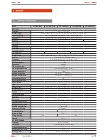
Model
Power (VA)
Nr outlets
Output terminals
SLC-700-TWIN
700
2
-
SLC-1000-TWIN
1000
2
-
SLC-1500-TWIN
1500
3
-
SLC-2000-TWIN
2000
3
-
SLC-3000-TWIN
3000
3
-
SLC-700-TWIN B1
700
2
-
SLC-1000-TWIN B1
1000
2
-
SLC-1500-TWIN B1
1500
3
-
SLC-2000-TWIN B1
2000
3
-
SLC-3000-TWIN B1
3000
3
-
SLC-700-TWIN R
700
4
-
SLC-1000-TWIN R
1000
4
-
SLC-1500-TWIN R B0
1500
4
-
SLC-2000-TWIN R B0
2000
4
-
SLC-3000-TWIN R B0
3000
-
1 set (F+N)
SLC-700-TWIN R B1
700
4
-
SLC-1000-TWIN R B1
1000
4
-
SLC-1500-TWIN R B1
1500
-
1 set (F+N)
SLC-2000-TWIN R B1
2000
-
1 set (F+N)
SLC-3000-TWIN R B1
3000
-
1 set (F+N)
Table 5.
Number of outlets and terminals depending on the
model
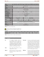
Never mind if the UPS is connected to any load, voltage could
8.
exist at its output. The internal parts of the equipment can
remain with voltage although the UPS is shutdown. Make sure
that there is no output voltage, disconnect the UPS and turn
off the input power supply in the electrical panel.
In case, it is needed to connect inductive loads to like laser
9.
printers, the inrush current of such loads should be calculated,
in order to determine if the UPS power rate is enough to supply
them.
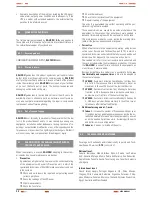
4.4.3. Procedure to connect the models with external
batteries, extended autonomies.
Do not make any connection between the UPS and battery
1.
modules, when the equipment and/or loads are turned on.
The DC nominal voltage of the external battery pack is 36 V DC
2.
(3 batteries of 12 V) for 0,7 kVA and 1 kVA equipments, and
96 V DC (8 batteries of 12 V) from 1,5 to 3 kVA equipments.
To achieve a higher autonomy, it is possible to connect some
battery packs.
Before connecting the battery modules to each
other and/or UPS, check that they have the same
voltage and capacity, otherwise the difference of
potential will provoke a short-circuit, which will cause dam-
ages to the UPS and/or to the battery modules.
Any connection between the UPS and battery module/s will
3.
be done taking care on the stated polarity in the equipment
labelling and the colour of the cables (red for positive, black for
negative and green yellow for the earth cable).
The connection with the batteries, either because they are
4.
supplied separate from the equipment or due to UPS extended
autonomy, will be done through the connector (C2) of the
equipment and (C2b) of the own battery module. Each battery
module has two identical connectors duly polarised too. One
of them is for the UPS connection and the other one is for the
connection with another battery module.
Insert one end of the cable into the connector (C2) of the UPS
5.
and the other end of the cable into the connector (C2b) of the
battery module. It is possible to link some battery modules by
means of the two connectors that each external battery unit
has, so one connector has to be connected to the preceded
module and the other one to next.
4.5.
COMMUNICATION PORTS..
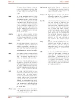
4.5.1. RS-232 interface (C7).
Pin #
Description
Input/Output
2
TxD
Output
3
RxR
Input
5
GND
Input
Table 6.
Pin-out of DB-9 connector (C7) RS232 interface
4.5.2. AS400 interface (C16) (Option).
Less the above communication protocol, this UPS series has an
AS400 communication protocol (optional). Contact with the dis-
tributor for more details.
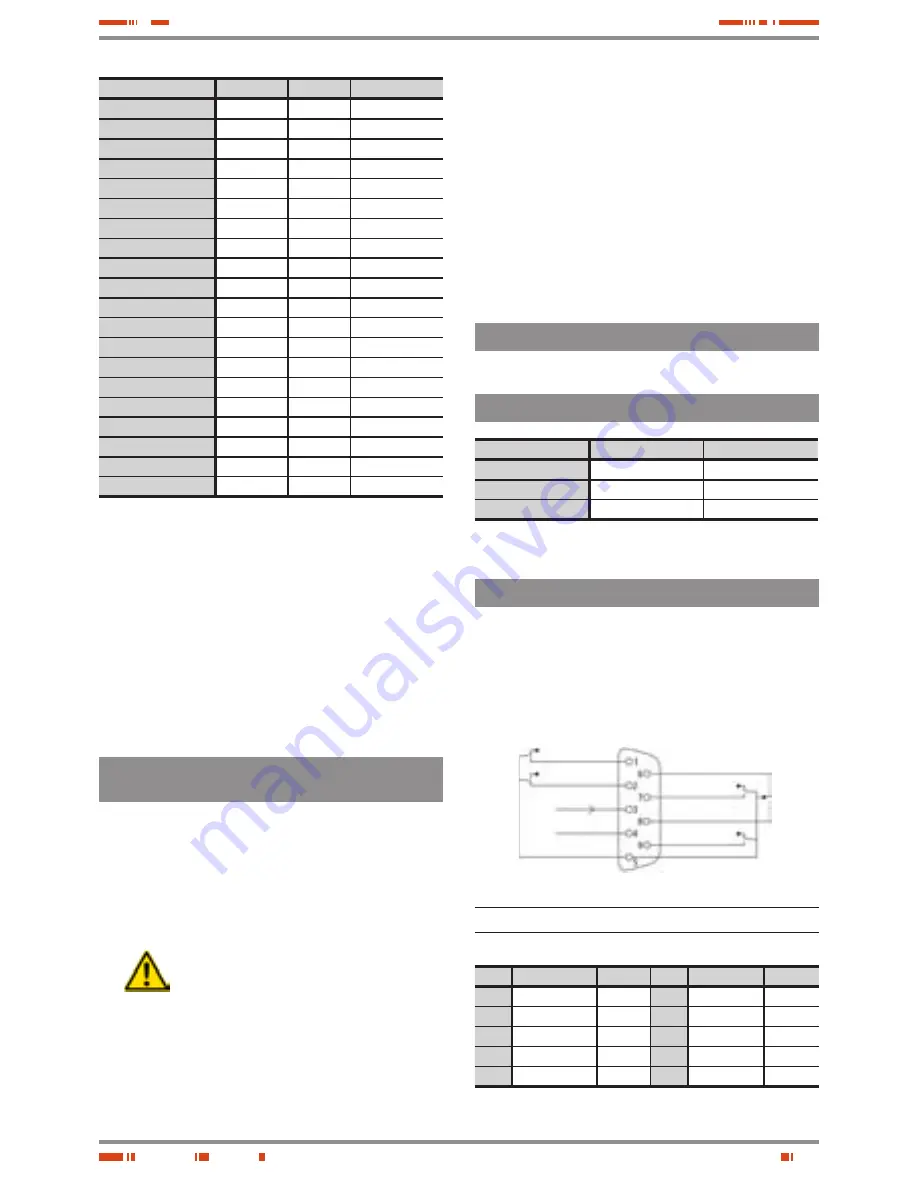
Pin-out and DB-9 connector description (C16) of the AS400 card.
UPS fault
General alarm
Ground (GND)
Remote shutdown
Common
Bypass
Low battery
UPS On
Mains fault
DB-9 connector (C16), AS400 interface
fig. 20.
Pin #
Description
I/O
Pin #
Description
I/O
1
UPS fault
Output
6
Bypass
Output
2
General alarm
Output
7
Low battery
Output
3
GND
Input
8
UPS ON
Output
4
Remote shutdown
Input
9
Mains fault
Output
5
Common
Input
Table 7.
Pin-out of DB-9 connector (C16), AS400 interface
Summary of Contents for SLC TWIN series
Page 3: ......
Page 29: ...28 NOTES USER MANUAL...
Page 30: ...29 SALICRU NOTES...
Page 31: ...30 NOTES USER MANUAL...
Page 32: ......
Page 35: ......
Page 60: ......


