background image

19

SALICRU

5.  OPERATING.

5.1. 

OPERATING MODE.

5.1.1.  Starting up the UPS with mains voltage (on Line 

mode).

Check both all the connections have been done properly and 

1. 

the input circuit breaker (M1), is not turned off. This protecion 
for  SLC-3000  TWIN  R  is  replaced  by  a  circuit  breaker,  turn 
«On» and also this model has an output fuse (M4), check that 
is fitted in and in good conditions.
Turn  «On»  the  distribution  panel  switch.  The  UPS  could  not 

2. 

supply power supply to the loads because the bypass mode is 
deactivated, code «00».
Start up the inverter of the UPS by pressing the button «On»  of 

3. 

the front panel for more than 1 second. The system will do an 
autotest and once finished the inverter will start up and also 
the UPS status will be displayed in the front LCD panel.

Note

: By default the equipment is set from factory with the by-

pass mode disabled, code «00», so the loads will not be supplied 
although there is voltage at the UPS input. To modify this factory 
setting, go to section 5.2.6 and activate the code «01».

5.1.2.  Starting up the UPS without mains voltage (on 

Battery mode).

Start up the inverter of the UPS by pressing the button «On»  of 

1. 

the front panel for more than 1 second. The system will do an 
autotest and once finished the inverter will start up and also 
the UPS status will be displayed in the front LCD panel. The 
period time that the UPS will remain started up will depend 
on the battery charging level and the loads connected at the 
UPS output.

5.1.3.  UPS shutdown with mains voltage (on Inverter mode).

Shutdown the inverter of the UPS by pressing the button «Off»  

1. 

in the front panel for more than 1 second. The UPS will go to 
no output mode «00» -bypass disabled- (code 00) or on bypass 
mode (code 01), depending if the initial setting has been modi-
fied or not. On bypass mode (code «01») the equipment will still 
be supplying output voltage through the bypass, so the input 
circuit breaker of the switchgear panel has to be turned off to 
shutdown the loads completely.

5.1.4.  UPS shutdown without mains voltage (on Battery 

mode).

To  shutdown  the  inverter  of  the  UPS,  just  press  the  button        

1. 

«Off» of the front panel for more than 1 second. The UPS will 
be turned off.

5.1.5.  Battery test function.

 To make a battery test with the equipment started up, press 

• 

the button « I » of the front panel or disconnect the input power 
supply to the UPS.

5.1.6.  Alarm silencer.

 To  silent  the  alarm  manually  with  the  equipment  on  battery 

• 

mode, press the button « I » of the front panel.
The  alarm  will  automatically  be  activated  when  the  battery 
capacity  is  low  (end  of  autonomy).  When  this  happens,  the 
loads have to be turned off and the UPS shutdown, because the 
equipment will break the output voltage in short.

5.2. 

CONTROL PANEL.

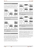
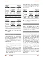
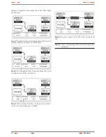
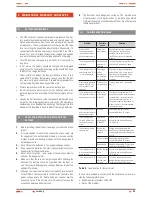
The different codes of operating, fault or warning can be displayed 
in the LCD panel of the synoptic, are described in the table 8. Some 
codes can be displayed or activated at any time, corresponding to 
modes of operating, warning or fault alarm or even though some 
alarms of fault together. Each one of these codes will be displayed 
in the screen of the display cyclically, less when one or more alarms 
are activated. In the last case, the display will only show the alarm 
or  the  alarms  cyclically,  not  being  displayed  the  operating  and 
warning modes.

Operating mode

Code

Operating mode

Code

Operating code

No output mode

00

Battery mode

03

Bypass mode

01

Battery test mode

04

Line mode

02

fault codes

Bus fault

05

Overload fault

07

Inverter fault

06

Overtemperature fault

08

Warning codes

Wiring error

09

Low battery

12

Fan or fans fault

10

Charger fault

13

Battery overvoltage

11

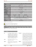
Table 8. 

Code list and their meaning

Summary of Contents for SLC TWIN series

Page 1: ...S L CT WI N I N D E X U S E R S MA N U A L F R O M0 7 k V AT O3 k V A P a g e 2 U S E R S MA N U A L F R O M4 k V AT O2 0 k V A P a g e 3 4...

Page 2: ...UPS VOLTAGE STABILIZERS AND POWER LINE CONDITIONERS SWITCH MODE POWER SUPPLY INDUSTRIAL POWER SUPPLY LIGHTING FLOW DIMMER STABILIZERS STATIC INVERTERS SLC TWIN series from 0 7 to 3 kVA USER S MANUAL...

Page 3: ......

Page 4: ...ng 4 4 2 Installation 4 4 3 Procedure to connect the models with external batteries extended autonomies 4 5 Communication ports 4 5 1 RS 232 interface C7 4 5 2 AS400 interface C16 Option 4 6 Overvolta...

Page 5: ...series This manual has to be read carefully before installing and operating it Keep this manual for future consults 1 2 1 Used symbols and conventions Warning symbol Carefully read the indicated para...

Page 6: ...InthenextPROCESSMAPisrepresentedtheinteractionamongallthe processes of the Quality and Environmental System of SALICRU 2 2 Standard The UPS product SLC TWIN series is designed manufactured and commer...

Page 7: ...ons of voltage frequencies electrical noises black outs and mains faults which are present in the energy distribu tion mains This is the essential target of the UPSs of SLC TWIN series This manual is...

Page 8: ...1 Input breaker protection Fan RJ 45 C7 RS232 communication port Rear view SLC 700 and 1000 TWIN TWIN B1 to 110 Fig 2 115 120 127 VAC C2 Extended autonomy connector C16 AS400 SNMP USB communication po...

Page 9: ...00 SNMP USB communication port optional C11 and C12 Transient protection Fax m dem C4 Outlet C0 Inlet M1 Input breaker protection Fan C7 RS232 communication port Rear view SLC 3000 TWIN to 208 220 230...

Page 10: ...m C4 Outlet C0 Inlet Fan Rear view SLC 700 and 1000 TWIN R TWIN R B1 Fig 8 C2 Extended autonomy connector C16 AS400 SNMP USB communication port optional C7 Communication port RS232 M1 Input breaker pr...

Page 11: ...some other usefull one are in the rear panel C2 Extended au tonomy connector C16 AS400 SNMP USB communication port optional C7 Communication port RS232 M1 Input breaker protection C11 and C12 Transie...

Page 12: ...Transient protection Fax modem C4 Outlets C0 Inlet Fans Rear view SLC 1500 TWIN R B1 Fig 14 C2 Extended au tonomy connector C16 AS400 SNMP USB communication port optional C7 Commu nication port RS232...

Page 13: ...owed from 0 to 999 Vac Hz It displays the frequency value of the output voltage which will be showed from 0 to 99 Hz Load information It displays the of the load in W or VA the maximum value will be s...

Page 14: ...MOD BAT TWIN 2x3AB003 40A R W C0 EE29503 Battery module special EE CO Silk screen printing Made in Spain in the equipment and packing customs topics W White label team R Rack format Protection caliber...

Page 15: ...IN series is card type in order to be inserted into the slot that UPS has in its rear side Thanks to this format it is avoided to have small devices around the UPS The connection from the UPS with the...

Page 16: ...e earth leakage currents at the UPS output plus the connected load s do not overcome 3 5 mA 4 1 4 Operating Do not disconnect the power cord plug of the UPS meanwhile the loads are turned on because t...

Page 17: ...2 6 hours before its use Once the input circuit breaker is turned On the UPS will charge the batteries automatically The UPS can be used immediately without charging the batteries previously but the...

Page 18: ...ifference of potential will provoke a short circuit which will cause dam ages to the UPS and or to the battery modules Any connection between the UPS and battery module s will 3 be done taking care on...

Page 19: ...e new UPS monitoring software which facilitates a friendly monitoring and control interface In case of mains failure this software gives an automatic Shutdown for a system made by several PCs With thi...

Page 20: ...epending if the initial setting has been modi fied or not On bypass mode code 01 the equipment will still be supplying output voltage through the bypass so the input circuit breaker of the switchgear...

Page 21: ...charges the batteries too The acoustic alarm of the UPS will beep once every 2 minutes The UPS doesn t have available the autonomy function when it runs on Bypass mode so if the mains faults the load...

Page 22: ...Operating mode screen Battery mode code 03 Fig 28 220Vac equipments 5 2 5 Fault mode Anyone of the fault or warning codes showed in the table 8 are considered as fault mode Besides some warning word c...

Page 23: ...ect of the LCD panel Step 2 The blinking black point is displayed beside 230 V after pressing twice the button Select Step 3 When pressing the button Enter for more than 1 second the new selected valu...

Page 24: ...or mainte nance job turn off the battery circuit breaker or remove the connection between battery blocks The batteries have dangerous voltages The maintenance 8 or replacement of the batteries has to...

Page 25: ...s guaranteed the perfect operating and the pos sible coming faults are avoided These supervisions are usually done without shutdown the equipment In those cases that a shutdown were needed a date and...

Page 26: ...3 THDv with non linear load 6 in accordance with EN 62040 3 Dynamic response time 150 ms Overload on line mode 150 for 30 s 150 for 0 3 s Overload on battery mode 150 for 30 s 150 for 0 3 s Permissib...

Page 27: ...ble 11 Output power derate according to the operating altitude 7 2 GlosSarY AC It is nominated as alternating current CA in Spanish abbreviation and AC in English to the electrical current in which th...

Page 28: ...d it is crossed by an electric current The colour wave longitude depends on the semiconductor ma terial used in its manufacturing being able to vary from the ultraviolet one going through the visible...

Page 29: ...28 NOTES USER MANUAL...

Page 30: ...29 SALICRU NOTES...

Page 31: ...30 NOTES USER MANUAL...

Page 32: ......

Page 33: ...RLANDA NORUEGA REP BLICA CHECA SUECIA SUIZA UCRANIA ARGENTINA BRASIL CHILE COLOMBIA ECUADOR PER ARABIA SAUD ARGELIA EGIPTO JORDANIA KUWAIT MARRUECOS T NEZ KAZAJST N PAKIST N FILIPINAS INDONESIA MALASI...

Page 34: ...UPS VOLTAGE STABILIZERS AND POWER LINE CONDITIONERS SWITCH MODE POWER SUPPLY INDUSTRIAL POWER SUPPLY LIGHTING FLOW DIMMER STABILIZERS STATIC INVERTERS UPS SLC TWIN series from 4 to 20kVA USER S MANUAL...

Page 35: ......

Page 36: ...4 Operating 4 1 5 Maintenance service and faults 4 2 To keep in mind 4 3 Unpacking and content checking 4 4 Connection of the input output and protective earth wiring 4 4 1 Notes for the installation...

Page 37: ...tion measures Danger of electrical discharge symbol Pay special attention to it both in the indication on the equipment and in the paragraph referred to this instruction s manual i Main protective ear...

Page 38: ...represented the interaction among all the processes of the Quality and Environmental System of SALICRU 2 2 Standard The UPS product SLC TWIN series is designed manufactured and commercialized in acco...

Page 39: ...ectrical noises blackouts and mains faults which are present in the energy distribution mains This is the essential target of the UPSs of SLC TWIN series Furthermore the 4 5 and 6kVA equipments can al...

Page 40: ...on port Intelligent slot Fans Input breaker Terminal strip cover Parallel port Maintenance bypass switch Rear view of the 12 15 and 20 kVA equipment bat Fig 3 tery cabinet 40 x 9Ah Communication port...

Page 41: ...m 0 to 999 Vac It displays the frequency value of the output voltage which will be showed from 0 to 99 Hz Load information It displays the of the load in W or VA the maximum value will be showed from...

Page 42: ...single phase UPS Power in VA KIT Equipments with two or more cabinets in a single code MOD BAT TWIN 2x3AB003 40A R W C0 EE29503 Battery module special EE CO Silkscreen Made in Spain in the equipment...

Page 43: ...r equipments with standard autonomy and adapts it to the optimal levels of the battery bank to charge This double conversion structure is complemented with two addi tional functional blocks the bypass...

Page 44: ...accepted by the main software and hardware manufacturers The available SNMP optional for TWIN series is card type in order to be inserted into the slot that UPS has in its rear side Thanks to this fo...

Page 45: ...ctrical shock risk Although the unit is disconnected from the electrical mains there are internal parts in the UPS that are still connected to the batteries therefore they are under dangerous voltage...

Page 46: ...e input and output cables to their corresponding 5 UPS terminals and according to the model circuit diagram i Tighten the connections The protective earth is the connection cable between the 6 equipme...

Page 47: ...eans the number of faulty UPSs that the system can allow simultaneously The higher is X the higher will be the reliability of the system For those occasions where the reliability is the essential N X...

Page 48: ...AINS FAULT REMOTE SHUTDOWN GENERAL ALARM UPS FAULT GND DB 9 interface of AS400 communication protocol Fig 13 4 8 Software Free software WinPower WinPower is the brand of the new UPS monitoring softwar...

Page 49: ...rocedure to add a new UPS 2 Before installing it prepare the input and output wiring a switches and parallel cable Turn OFF the input and output breakers of the new unit b Connect its input output and...

Page 50: ...ed OFF Do not touch the maintenance switch meanwhile the c system runs on inverter mode 5 3 CONTROL Panel All the codes will be displayed in the LCD panel corresponding to their operating modes as fol...

Page 51: ...one those loads that are not critical in order to decrease the load percentage under 90 of the UPS nominal power rate Note To connect a generator or genset proceed as follows Turn on the generator an...

Page 52: ...ternated between the Pn symbol and the code of the mode The P symbol means that the UPS runs on Parallel mode and n number means the parallel quantity Warning mode 6 The LCD panel on Warning mode is s...

Page 53: ...cy or By pass status will be modified by the selected one In case the ENTER or Select buttons are not pressed in 10 seconds period the black point will disappear without applying any changes Only one...

Page 54: ...ing should start when the UPS would have shutdown due to a deep battery discharge The charge time for a standard UPS should 12 hours as minimum 6 2 Notes for installing and replacing the battery Befor...

Page 55: ...e load and reduce the number of loads connected to the UPS Check that they are not damaged The Warning mode is 23 the buzzer beeps every second The UPS charger is faulty Contact with the technical ser...

Page 56: ...s are avoided These supervisions are usually done without shutdown the equipment In those cases that a shutdown were needed a date and time would agree with the customer to do the task This maintenanc...

Page 57: ...the output is broken Internal charger Technology DC DC Flyback Charge type P U Constant power constant voltage Floating voltage accuracy 1 V Maximum charging current 2 A single phase input 4 A three p...

Page 58: ...romag netic interference considerably EMi is the perturbation that occurs in a radio transmis sion or any other electrical circuit caused by an electromagnetic perturbation coming from an external sou...

Page 59: ...nt This isdoneby rectifier diodes which can be solid state semiconduc tors vacuum or gassy valves like the mercury vapour Depending on the features of the alternating current power supply used it is c...

Page 60: ......
Page 61: ...NAMARCA GRECIA HOLANDA IRLANDA NORUEGA REP BLICA CHECA SUECIA SUIZA UCRANIA ARGENTINA BRASIL CHILE COLOMBIA ECUADOR PER ARABIA SAUD ARGELIA EGIPTO JORDANIA KUWAIT MARRUECOS T NEZ KAZAJST N PAKIST N FI...

Reviews: