26
SALICRU
•
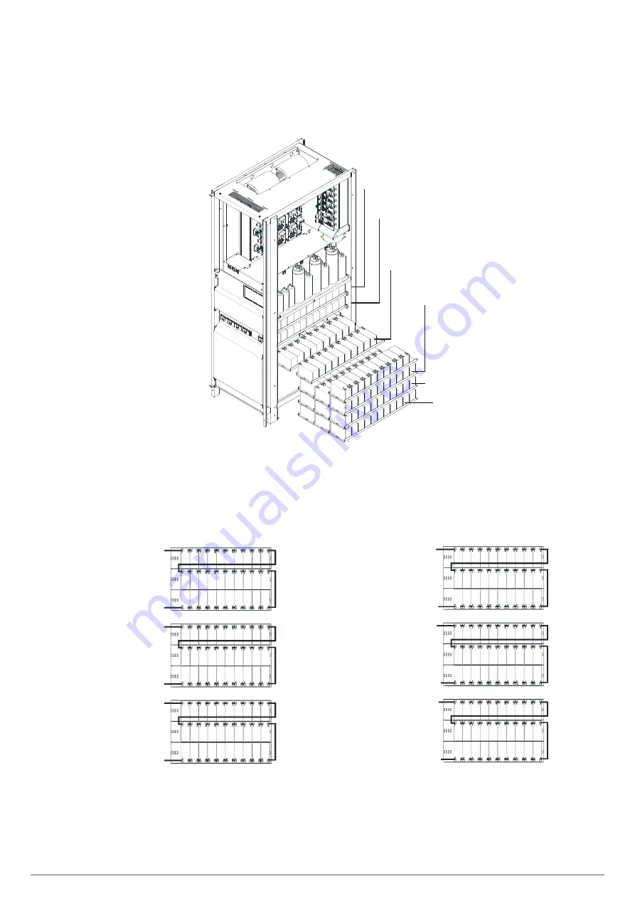
80 kVA device: installation of 12 V and 7-9-11 Ah
batteries.
Remove the 6 screws to open the left/right side cover
and access the battery tray (there are a total of 6 trays,
each containing 3 rows of 10 batteries).
Tray 1:
rows 1 to 3
Tray 2:
rows 4 to 6
Tray 3:
rows 7 to 9
Tray 4: rows
10 to 12
Tray 5: rows
13 to 15
Tray 6: rows
16 to 18
Fig. 26.
Side view of the battery trays
(12 V, 7-9-11 Ah).
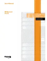
Install the batteries received in separate packages as
indicated in Fig. 27 and Fig. 29:
Tray 1
Tray 3
Tray 2
Battery fuse negative
Battery fuse
negative
Battery fuse
negative
Battery neutral
Battery neutral
Battery neutral
Tray 6
Battery neutral
Battery fuse
positive
Tray 2
Tray 4
Battery neutral
Battery fuse
positive
Battery fuse
positive
Battery neutral
Fig. 27.
Top view of the battery connection tray
(12 V, 7-9-11 Ah).
Summary of Contents for SLC X-PERT 100
Page 1: ...SLC X PERT 80 400 kVA UNINTERRUPTIBLE POWER SUPPLIES UPS USER MANUAL...
Page 8: ...8 SALICRU Fig 3 Front view of the 400 kVA model...
Page 34: ...34 SALICRU Fig 42 Connection of three UPSs through the CAN bus for 400 kVA devices...
Page 60: ...60 SALICRU...
Page 61: ...61 X PERT UNINTERRUPTIBLE POWER SUPPLIES UPS USER MANUAL...


