43
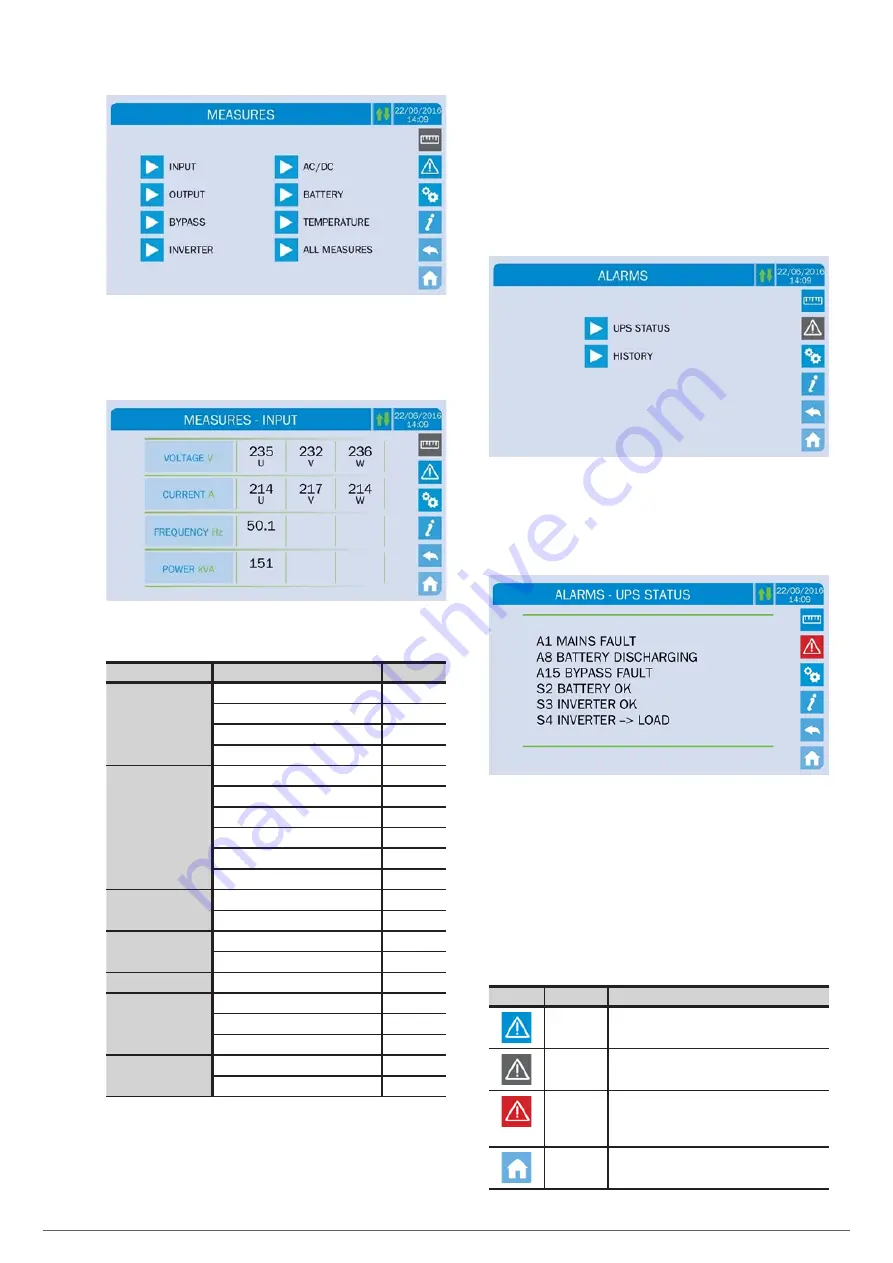
Fig. 56.
Measures section.
To enter the measures page of a specific section of the UPS,
it is necessary to press one of the arrows. Below is a page of
typical measures.
Fig. 57.
Input measures page.
List of all of the measures available.
Submenu/Subpage
Displayed data
Accuracy
INPUT
Rectifier input voltage
(1)
1 V
Rectifier input current
1 A
Frequency
0.1 Hz
Input power
1 kVA
OUTPUT
Voltage
(1)
1 V
Current
1 A
Load percentage
1%
Active power
1 kW
Apparent power
1 kVA
Frequency
0.1 Hz
BYPASS
Voltage
(1)
1 V
Frequency
0.1 Hz
INVERTER
Voltage
(1)
1 V
Frequency
0.1 Hz
AC / DC
Rectifier output voltage
1 V
BATTERY
Voltage and current
1 V / 1 A
Rated capacity
1 Ah
Residual backup
1 min / 1%
TEMPERATURE
(2)
Batteries
0.1 °C
UPS
0.1 °C
Tabla 16.
Data that can be viewed in the Measures
section/menu.
(1)
Voltage measurements always refer to the phase-neutral value.
(2)
Temperatures are displayed only if the probe is installed
.
7.2. BASIC DIAGNOSTICS.
By pressing the alarm icon on the control panel, the current
operating status of the device is shown and the event log is
accessed.
The UPS STATUS submenu displays the alarms present and the
operating conditions. The HISTORY menu shows the event log.
Fig. 58.
SLC X-PERT UPS Alarms section.
7.2.1. Display of operating states.
By pressing UPS STATUS, the operating status of the UPS and
possible active alarms will be shown.
Fig. 59.
UPS STATUS subpage of the Alarms section of
the device.
If the list exceeds the capacity of a page (8 lines), it can be
moved by sliding a finger across the screen.
7.2.2. Icon colours.
The Alarm and Home page icons can change colour depending
on the condition of the UPS and the screen being displayed.
Icon
Colour
Meaning
Light blue
Dark blue
No alarms activated.
Grey
No alarms activated.
A page of the Alarms section is displayed.
Red
Alarm activated. If the alarm affects one of the
modules, the corresponding icon on the Home
page will change colour to orange or red.
Light blue
No alarms activated.
X-PERT
UNINTERRUPTIBLE POWER SUPPLIES (UPS)
USER MANUAL
Summary of Contents for SLC X-PERT 100
Page 1: ...SLC X PERT 80 400 kVA UNINTERRUPTIBLE POWER SUPPLIES UPS USER MANUAL...
Page 8: ...8 SALICRU Fig 3 Front view of the 400 kVA model...
Page 34: ...34 SALICRU Fig 42 Connection of three UPSs through the CAN bus for 400 kVA devices...
Page 60: ...60 SALICRU...
Page 61: ...61 X PERT UNINTERRUPTIBLE POWER SUPPLIES UPS USER MANUAL...


