13
Check that the maintenance personnel have been
trained.
The UPS’s operation and control devices must only be used
by authorised personnel. It is recommended to check that the
personnel responsible for the use and maintenance of the
system have been trained.
4.7.1. Circuit breakers.
The UPS’s circuit breakers are used to isolate the device from
the AC power mains, the storage batteries and the load.
Presence of voltage in device terminals.
The circuit breakers do not isolate the UPS completely,
since the AC voltage is still present in the input terminals of
the UPS. Before performing any maintenance on the unit, it is
necessary to:
–
Isolate the UPS completely by activating the
external switches.
–
Wait at least 5 minutes to allow the capacitors to
discharge.
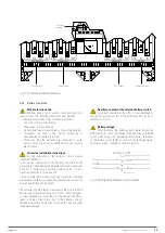
4.7.2. Emergency power off button (EPO).
The emergency power off button is used to disconnect the UPS
output immediately, interrupting the powering of the loads. It
also turns off the inverter.
Only press the button in case of emergency.
The components of the system are subjected to high
stress when the button is pressed in the presence of load.
Only press the button in case of real emergency.
Restoring the power supply.
Restore the output power supply only when the causes
of the emergency shutdown have been eliminated and it is
certain that there is no danger to people or devices.
4.7.3. Normal/Bypass selector.
The Normal/Bypass selector can be found on the top front of
the device when the door is opened. It is usually used during
the manual bypass procedure, when it is necessary to isolate
the UPS for maintenance or repair work.
Follow the procedures in the manual.
The Normal/Bypass selector should only be operated by
following the steps established in the relevant chapter of this
document. The user will be solely responsible for any faults
caused to the UPS, loads and/or installation as a result of
incorrect actions.
4.7.4. Control panel with LCD.
The UPS’s control panel is used to:
Check the device’s operating parameters.
Check the alarms present.
Access the event history.
Display the information on the device.
Modify the operating parameters.
The menu enables modification of the setting parameters and
is protected by a password to prevent access by unauthorised
personnel.
4.8. OPTIONAL EXTRAS.
Depending on the configuration chosen, the device can include
any of the following options:
4.8.1. Isolation transformer.
The isolation transformer provides galvanic isolation in order
to completely isolate the output from the input and/or change
the neutral point treatment. The placement of an electrostatic
screen between the primary and secondary windings of the
transformer provides a high level of electrical noise attenuation.
The isolation transformer can be physically placed at the input
or output of the UPS depending on the technical conditions of
the whole system (device supply voltage and/or load voltage,
their characteristics or type, etc.). This component can be
installed within the 80 kVA device, connecting the batteries
externally. It will always be supplied as a peripheral component
external to the device itself in a separate enclosure.
4.8.2. External manual maintenance bypass.
The purpose of this option is to electrically isolate the device
from the mains and the critical loads without cutting the power
to the latter. In this way, maintenance or repair operations on
the device can be carried out without interruptions to the power
supply of the protected system, while preventing unnecessary
hazards for technical personnel.
4.8.3. Communication card.
The UPS features a slot at the rear for inserting one of the
following communication cards:
4.8.3.1. Integration into computer networks using an SNMP adapter.
Large computer systems based on LANs and WANs that
integrate servers in different operating systems must provide
the system manager with ease of control and administration.
This facility is obtained through an SNMP adapter, which
is universally supported by the main software and hardware
manufacturers. Connection of the UPS to the SNMP is internal
while that of the SNMP to the computer network is made
through an RJ45 10 base connector.
4.8.3.2. RS-485 MODBUS.
Large computer systems based on LANs and WANs often
require that communication with any element that is integrated
into the computer network be made through a standard
industrial protocol, MODBUS being one of the most used. The
SLC X-PERT series can also be integrated into these types of
environment using an RS-485 MODBUS card.
X-PERT
UNINTERRUPTIBLE POWER SUPPLIES (UPS)
USER MANUAL
Summary of Contents for SLC X-PERT Series
Page 1: ...SLC X PERT 80 400 kVA UNINTERRUPTIBLE POWER SUPPLIES UPS USER MANUAL...
Page 8: ...8 SALICRU Fig 3 Front view of the 400 kVA model...
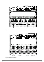
Page 34: ...34 SALICRU Fig 42 Connection of three UPSs through the CAN bus for 400 kVA devices...
Page 60: ...60 SALICRU...
Page 61: ...61 X PERT UNINTERRUPTIBLE POWER SUPPLIES UPS USER MANUAL...


