17
Cable-
routing
plate
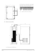
855
42.5
66
1298
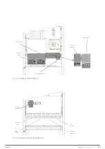
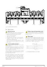
Fig. 14.
Plan view of the base of 400 kVA devices.
The UPS’s support base must be designed to support its weight
and guarantee its stability. Its load capacity must be appropriate
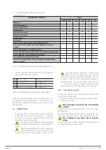
for the static loads indicated in the following table:
Power (kVA)
80
100
125
160
200
250
300
400
Weight (kg)
300
320
360
380
720
850
900
1080
Static load
(kg/m
2
)
590
630
710
750
1120
1280
1395
1390
Tabla 1.
Weight and static load for each device.
5.1.7. Dimensions, space and ventilation.
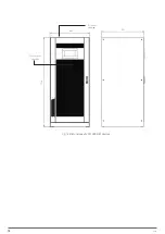
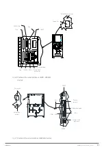
Air outlet
openings
Air inlet
openings
948.5
552
1801
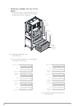
Fig. 15.
Dimensions of 80... 160 kVA devices.
X-PERT
UNINTERRUPTIBLE POWER SUPPLIES (UPS)
USER MANUAL
Summary of Contents for SLC X-PERT Series
Page 1: ...SLC X PERT 80 400 kVA UNINTERRUPTIBLE POWER SUPPLIES UPS USER MANUAL...
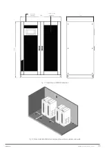
Page 8: ...8 SALICRU Fig 3 Front view of the 400 kVA model...
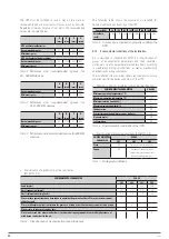
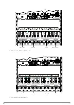
Page 34: ...34 SALICRU Fig 42 Connection of three UPSs through the CAN bus for 400 kVA devices...
Page 60: ...60 SALICRU...
Page 61: ...61 X PERT UNINTERRUPTIBLE POWER SUPPLIES UPS USER MANUAL...


