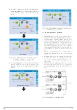
31
Selector Normal/Bypass
MODBUS SRC-2 Paralelo: Sincro-
nismo carga
Installation and start-up of INGENIO MAX UPS 200-250-300 kVA
Installazione e avviamento INGENIO MAX UPS 200-250-300 kVA
OMP06119 REV. F
35
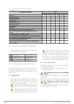
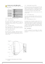
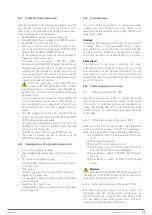
4.5.4 Remote emergency power off (EPO)
Auxiliary EPO contact on terminals X10-7/8.
The voltage supply to the loads can be interrupted from a remote location by using this contact
(i.e. for safety requirements). A normally closed contact is required; when this contact is open
the static inverter and by-pass switches are opened so that the output supply is interrupted.
In case the external EPO command is not provided short-circuit the terminals 7-8.
4.5.5 Battery auxiliary contact
Battery auxiliary contact on terminals X10-9/10.
This auxiliary contact is necessary to indicate the position of the isolator (open-closed).
4.5.6 Diesel Generator auxiliary contact
Auxiliary contact from the Diesel Generator on terminals X10-11/12.
A normally open contact must be used; the contact must close when the diesel generator is
operating.
The microprocessor will acquire the status of the contact and, upon the rectifier start-up, it will
enable the "Diesel Mode" operation, that is the operation at reduced DC voltage in order to
reduce the power drawn from the AC line.
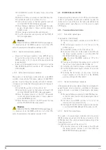
4.6 SERIAL INTERFACES AND EXTERNAL CONNECTIONS
The UPS is provided with serial interfaces and external connection facilities for the
communication of the operating status and parameters.
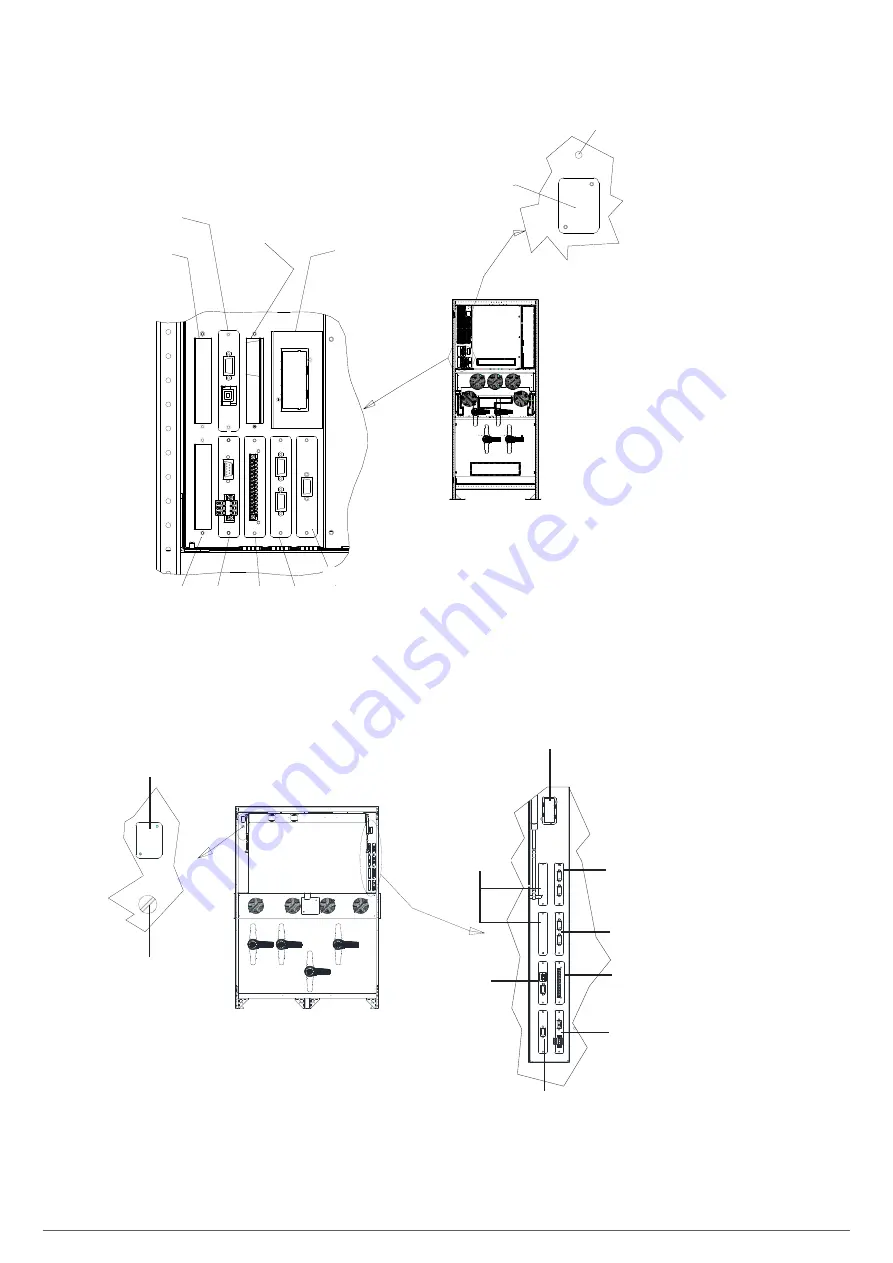
Picture 8 – Position of the serial interfaces of INGENIO MAX 200-250-300 kVA
Slot de servicio
SNMP
Libre
Libre
Libre
RS232/USB
Sonda térmica
Installa
tion
and start
-up of
IN
GENIO M
AX UPS
200-250
-300
kVA
Installaz
ione e av
viamento INGEN
IO M
AX UP
S 200
-250
-300
kVA
OMP0611
9 REV
. F
35
4.5.4
Remote
emergency
power
off (EPO)
Aux
iliary
EP
O contact
on te
rmin
als
X10
-7/
8.
The
vol
tage
supply
to th
e lo
ads can
be in
terrupted
fro
m a
remo
te lo
catio
n by
usi
ng this
contac
t
(i.e. for
sa
fety
requi
rements).
A normall
y clo
sed contact
is re
qui
red; w
hen this
contact is
open
the stat
ic inv
erter
and by-pass
switches are
opened so
that the ou
tput suppl
y is interr
upted.
In case
the exter
nal EP
O command
is not pr
ovid
ed shor
t-cir
cuit the
terminal
s 7-8.
4.5.5
Battery
auxilia
ry con
tact
Battery
auxilia
ry contact on te
rmin
als
X10
-9/
10.
Thi
s auxilia
ry contact
is
necessary
to indi
cate the position
of the isol
ator (
open-clo
sed).
4.5.6
Diesel Genera
tor auxi
liary contact
Auxi
liary
contact fr
om th
e Diesel
Gene
rator
on
te
rmin
als
X10
-11
/12.
A normall
y open
contact
must
be used
; the
contact
mus
t clo
se w
hen the
diesel
g
enerator
is
operating.
The
microprocesso
r w
ill acq
uire
the stat
us of
the
contact
and,
upon the
recti
fie
r start
-up
, it
will
enable
the
"Diesel
M
ode"
operation,
that is
the operation
a
t redu
ced D
C vol
tage
in order
to
reduce the
power
draw
n fro
m the AC line.
4.6
SERI
AL INTERF
ACE
S A
ND EXTERN
AL C
ONNECTIONS
The
UPS
is
provid
ed w
ith serial
in
terfaces
and
exter
nal
connect
ion
faci
lities
f
or
the
communi
cation o
f the operatin
g s
tatus and
param
eters.
Picture
8
– Po
sition
of th
e s
erial interfaces
of
INGENIO
M
AX
200
-25
0-30
0 k
VA
Normal/Bypass selector
Parallel: Load
synchronism
Service slot
Free
Free
Free
Thermal probe
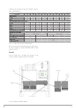
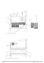
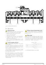
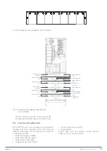
Fig. 36.
Position of the serial interfaces of 200... 300 kVA
devices.
SNMP
Slot de
servicio
Selector
Normal / Byp
Libre
Batería común
SCR-2
RS485
RS232 - USB
Paralelo - Sincro-
nismo carga
Sonda temperatura
Service slot
Normal/Byp
selector
Free
Common
battery
Parallel - Load
synchronism
Temperature probe
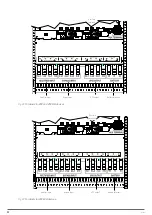
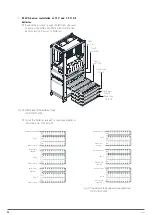
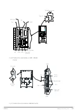
Fig. 37.
Position of the serial interfaces of 400 kVA devices.
X-PERT
UNINTERRUPTIBLE POWER SUPPLIES (UPS)
USER MANUAL
Summary of Contents for SLC X-PERT Series
Page 1: ...SLC X PERT 80 400 kVA UNINTERRUPTIBLE POWER SUPPLIES UPS USER MANUAL...
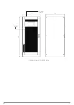
Page 8: ...8 SALICRU Fig 3 Front view of the 400 kVA model...
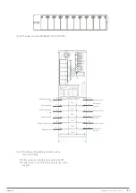
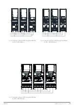
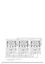
Page 34: ...34 SALICRU Fig 42 Connection of three UPSs through the CAN bus for 400 kVA devices...
Page 60: ...60 SALICRU...
Page 61: ...61 X PERT UNINTERRUPTIBLE POWER SUPPLIES UPS USER MANUAL...

