background image

4

SALICRU

1.  INTRODUCTION.

1.1.  THANK YOU LETTER.

We thank you in advance for the confidence you placed in 

us by purchasing this product. Read this instruction manual 

carefully in order to familiarise yourself with its content, since 

the more you know and understand the device the greater 

your satisfaction, level of safety and optimisation of its 

functionalities will be.

We remain at your disposal for any additional information or 

queries that you may wish to make.

Yours sincerely.

SALICRU


The device described here 

is capable of causing sig-

nificant physical injury if improperly handled

. For this 

reason, its installation, maintenance and/or repair must 

be carried out exclusively by our staff or by 

qualified per-

sonnel

.


Although no effort has been spared to ensure that the in-

formation in this user manual is complete and accurate, 

we accept no liability for any errors or omissions that may 

exist. 


The images included in this document are for illustrative 

purposes and may not exactly represent the parts of the 

device shown; therefore they are not contractual. However, 

any divergence that may arise will be remedied or solved 

with the correct labelling on the unit.


Following our policy of constant evolution, 

we reserve 

the right to modify the characteristics, operations 

or actions described in this document without prior 

notice

.


Any 

reproduction, copying, assignment to third par-

ties, amendment or total or partial translation

 of this 

manual or document, in any form or by any means, 

without 

the prior written permission of Salicru is prohibited

with the company fully and exclusively reserving its owner-

ship rights over it.

Summary of Contents for SLC X-PERT Series

Page 1: ...SLC X PERT 80 400 kVA UNINTERRUPTIBLE POWER SUPPLIES UPS USER MANUAL...

Page 2: ...onintocomputernetworksusinganSNMPadapter 4 8 3 2 RS 485MODBUS 4 8 3 3 Relayinterface 5 INSTALLATION 5 1 RECEPTIONOFTHEDEVICE 5 1 1 Reception unpackingandcontents 5 1 2 Storage 5 1 3 Unpacking 5 1 4 Tr...

Page 3: ...Restartingthehistory 7 3 5 RS 485interfaceparameters 7 3 6 Batterysetting 7 3 6 1 Installinganewbattery 7 3 6 2 Batteryconfiguration 7 3 6 3 Batterytest 7 3 7 UPStest 7 3 8 Networkparameterconfigurat...

Page 4: ...sonnel Although no effort has been spared to ensure that the in formation in this user manual is complete and accurate we accept no liability for any errors or omissions that may exist The images inc...

Page 5: ...nd startup operations to be performed in a simple and organised manner without any doubts whatsoever Finally once the equipment is installed and operating it is recommended to save the documentation d...

Page 6: ...t liable in the event of modifica tion or intervention on the device by the user WARNING The SLC X PERT is a category C3 UPS It is a product for commercial and industrial application in the second env...

Page 7: ...owever discrepancies or slight contradictions may arise If in any doubt the labelling on the device itself will always prevail See the nameplate of the device to verify all of the valuesrelatingtoitsm...

Page 8: ...8 SALICRU Fig 3 Front view of the 400 kVA model...

Page 9: ...s packaging etc 3x380 V Input and output voltage Disregard if it is 3x400 N B1 Device with external batteries for non standard backup 3x60AB265 Device with internal batteries only 80 kVA SYNC External...

Page 10: ...OPERATING PRINCIPLE 4 5 1 Rectifier The rectifier converts three phase AC mains voltage into direct DC voltage It uses a fully controlled three phase IGBT bridge with low harmonic absorption The cont...

Page 11: ...ced DC voltage a control algorithm allows the batteries to be reconnected periodically for recharging purposes intermittent charging Mains Mains Output Fig 7 High Efficiency operation When the High Ef...

Page 12: ...e loads from the moment the bypass is enabled Manual inverter The output power is not restored automatically The system requires a confirmation to restart which can be done manually by the user throug...

Page 13: ...and is protected by a password to prevent access by unauthorised personnel 4 8 OPTIONAL EXTRAS Depending on the configuration chosen the device can include any of the following options 4 8 1 Isolation...

Page 14: ...e between the device and other machines or devices through the relays of the terminal block on the same card featuring a single common terminal for all of them From the factory all contacts are normal...

Page 15: ...ut in accordance with current laws We recommend keeping the packaging for at least 1 year 5 1 2 Storage The device should be stored in a dry ventilated location protected from rain dust water splashes...

Page 16: ...recommended for the UPS itself For extended backups with more than one cabinet it is recommended to place one on each side of the device and in the case of a greater number of battery cabinets repeat...

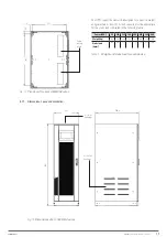
Page 17: ...he static loads indicated in the following table Power kVA 80 100 125 160 200 250 300 400 Weight kg 300 320 360 380 720 850 900 1080 Static load kg m2 590 630 710 750 1120 1280 1395 1390 Tabla 1 Weigh...

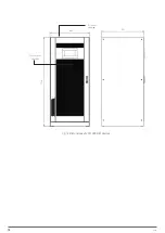
Page 18: ...18 SALICRU 880 1978 947 Air outlet openings Front air inlet openings Fig 16 Dimensions of 200 300 kVA devices...

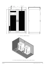
Page 19: ...let openings Front air inlet openings 1430 1978 948 Fig 17 Dimensions of 400 kVA devices Fig 18 Recommended distances between the various cabinets and walls X PERT UNINTERRUPTIBLE POWER SUPPLIES UPS U...

Page 20: ...logical conditions as well as mechanically and chemically active substances The installation site must meet certain requirements to ensure compliance with the design conditions of the UPS Weather cond...

Page 21: ...eet the indicated requirements it will be necessary to take additional precautions to reduce values in excess of the specified limits 5 2 CONNECTIONS A bad connection or switching operation can cause...

Page 22: ...3x 1x95 3x 1x95 3x 1x150 3x 1x185 3x 2x150 3x 2x185 3x 2x240 Earth conductor cross section mm2 35 50 50 95 95 150 185 240 CONNECTION TO THE MAINS Type Screw terminals Aluminium bars Max conductor cros...

Page 23: ...minals Rectifier input UPS output Fig 20 Terminals for 100 kVA devices Battery terminals Auxiliary terminals Rectifier input UPS output Bypass input Fig 21 Terminals for 125 and 160 kVA devices X PERT...

Page 24: ...UPS UPS OUTPUT B N B 3 N N RISPETTARE LA POLARITA PLEASE RESPECT POLARITY BATTERIA BATTERY Fig 22 Terminals for 200 and 250 kVA devices Installation and start up of INGENIO MAX UPS 200 250 300 kVA In...

Page 25: ...urer the operating temperature should remain between 0 and 25 C Batteries can however work up to 40 C with a significant reduction of its service life In order to avoid the formation of any kind of mi...

Page 26: ...rows 13 to 15 Tray 6 rows 16 to 18 Fig 26 Side view of the battery trays 12 V 7 9 11 Ah Install the batteries received in separate packages as indicated in Fig 27 and Fig 29 Tray 1 Tray 3 Tray 2 Batte...

Page 27: ...eutral Battery neutral Battery neutral Battery fuse positive Battery neutral Battery fuse positive Battery neutral Battery fuse positive B B N B N N B B N B N N Fig 29 Front view of the battery connec...

Page 28: ...12 Tray 5 rows 13 to 15 Tray 6 rows 16 to 18 Fig 30 Side view of the battery trays 12 V 12 14 Ah Install the batteries received in separate packages as indicated in Fig 31 and Fig 32 Battery fuse nega...

Page 29: ...ter connection insert the trays back into the UPS Replace and fix the left right cover with the screws 5 2 3 Connection of the auxiliary cables SLC X PERT UPS units can be connected to controls extern...

Page 30: ...he loads can be interrupted from a remote location by using this contact A normally closed contact is required when it is open the static inverter and bypass switches will open and the output power su...

Page 31: ...XTERNAL The UPS is provided with serial interfaces an communication of the operating status and parameter Picture 8 Position of the serial interfaces of INGENIO MA the static inverter and by pass swit...

Page 32: ...tely The electrical connection is made directly to the terminals located on the front of the SRC 2 interface slot SRC 2 slot Common alarm Mains failure End of battery backup Inverter out of tolerance...

Page 33: ...ndante e di potenza INGENIO 60 80 100 125 160kVA Transformerless Manuale operativo OML46016 Rev A 23 Picture 11A Es BUS CAN Connection 3 INGENIO PLUS 125 160kVA NOTE It s recommended to use cables wit...

Page 34: ...34 SALICRU Fig 42 Connection of three UPSs through the CAN bus for 400 kVA devices...

Page 35: ...is within operating values The phase rotation phase sequence of the line is correct and the voltage is within the tolerance of the operating values The emergency power off button EPO if installed is n...

Page 36: ...closing the RCB the LCD remains switched off 1 Check the phase rotation of the supply voltage 2 Verify that the input voltage and frequency are within tolerance 3 Check rectifier protection fuses F1 F...

Page 37: ...e inverter shuts down and the load is powered by the input mains via the manual bypass switch The static bypass switch is closed and LED 8 is shown in orange The screen continues to show alarm A30 3 S...

Page 38: ...of the system which guarantees continuity of supply even if more than one failure is detected This is possible because all of the units operate and constantly power the loads in parallel each of them...

Page 39: ...load Availability of n 1 bypass lines Load powered by the bypass in case of at least two inverter faults or overload 6 4 3 System behaviour The static and dynamic behaviour of the parallel system impr...

Page 40: ...rnal cabinets to Off 6 5 POWER PARALLEL SYSTEM The power parallel system consists of n UPSs up to a maximum of 6 units configured as parallel units in addition to power If a failure occurs in one of t...

Page 41: ...e MBCB manual bypass switches on all of the units to Off Following the instructions shown on the screen move the bypass selectors of all of the units to the NORMAL position starting with UPS number 1...

Page 42: ...the UPS In general the basic colours are Light blue indicates that the section is related to the UPS Grey the keys turn grey disabled when you enter the specific section of the key Red the Alarms key...

Page 43: ...led 7 2 BASIC DIAGNOSTICS By pressing the alarm icon on the control panel the current operating status of the device is shown and the event log is accessed The UPS STATUS submenu displays the alarms p...

Page 44: ...medium is inserted and the corresponding icon changes from grey to blue enabled The text file saved contains the same information as the history as well as a description of each event Fig 61 Save the...

Page 45: ...essed Alarms are displayed when they are present and must be muted by cancelling the audible alarm Alarms remain visible while they are present and are automatically stored in the event log Descriptio...

Page 46: ...abled due to disconnection of two parallel cables alarm A55 System restart after shutdown due to EPO activation For a description of the status of the UPS in each of the possible failures mentioned se...

Page 47: ...g 69 Battery parameters setting example 7 3 6 3 Battery test The BATTERY TEST menu allows you to perform a short battery discharge test If the batteries are not efficient alarm A10 Battery failure is...

Page 48: ...to VFD mode voltage dependent on frequency or line interactive In this mode the load is powered directly by the AC mains and the inverter is switched on ready to take over in case of mains malfunction...

Page 49: ...n that unit A question mark next to a number indicates that the UPS is not communicating on the data bus For example let us assume that we have the following situation System composed of 4 UPSs UPS2 i...

Page 50: ...diagnostics that allow immediate visualisation of the operating conditions In case of alarm the corresponding red icon on the control panel will light up and the audible alarm will be activated if en...

Page 51: ...itch waiting for the inverter to restart State S8 INV MASTER SYNC Description The inverter is synchronised with the MASTER UPS Operating state This state only appears in the SLAVE UPS units and indica...

Page 52: ...ier s voltage has been reduced to start a brief controlled discharge of the batteries Battery test started automatically or manually by user Wait until end of test and check for possible battery malfu...

Page 53: ...ed which disables a part of the UPS rectifier inverter static switch System fault Check which alarms present and follow procedure indicated A29 MAINT REQUIRED Maintenance needed Time limit since last...

Page 54: ...tery probe is installed and enabled Abnormal temperature inside external battery cabinet Possible fault in measuring circuit Check temperature of batteries and eliminate cause of alarm A53 FIRMWARE ER...

Page 55: ...an be performed by qualified personnel familiar with them No other person should handle them Depending on the configuration of the UPS certain actions need to be carried out before handling the batter...

Page 56: ...No battery cells lead 360 372 Protection rating IP20 Electromagnetic compatibility EN IEC 62040 2 CE marking Safety EN IEC 62040 1 Operation and test EN IEC 62040 3 Quality and Environment ISO 9001 I...

Page 57: ...tartup ramp time walk in s 5 30 programmable Sequential startup hold off s 1 300 programmable BATTERIES Battery type standard Sealed lead acid VRLA maintenance free Number of cells 360 372 Float volta...

Page 58: ...1 5 Requirement compliance Max crest factor without degradation 3 1 BYPASS Automatic bypass Electronic thyristor Input 3 phases 4 wires Protection Fuses External Three phase rated input voltage sel Va...

Page 59: ...ata presentation formed by 2 transparent conductive layers and a special crystalline material in the middle liquid crystal which have the ability to orientate light as it passes through LED Light emit...

Page 60: ...60 SALICRU...

Page 61: ...61 X PERT UNINTERRUPTIBLE POWER SUPPLIES UPS USER MANUAL...

Page 62: ...icru_SA Product Range Uninterruptible Power Supplies UPS Stabilisers Step Down Light Dimmers Power Supplies Static Inverters Photovoltaic inverters Voltage Stabilisers Variable Frequency Drives Inform...

Reviews: