42
SALICRU
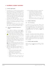
7. CONTROL PANEL.
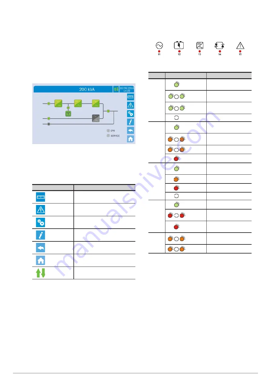
Devices from the X-PERT 200... 400 kVA series feature a
10.1 inch touch screen that dialogues with the I/O (input/
output) module of the control logic via a serial protocol. The
Home screen shows a flow diagram of the system, from which
all of the operating variables of the UPS can be accessed.
In addition, LEDs can be found on the frame of the control panel
(see Fig. 53), with the meanings described in Table 13.
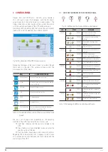
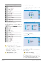
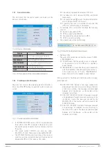
Fig. 54.
Front panel of the UPS. Home screen.
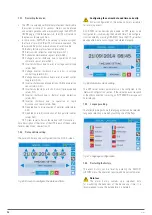
Navigating the pages of the touch screen is possible through
the 6 icons on the right. The up/down arrows control the
communication of the screen.
ICON
ASSIGNED FUNCTIONS
Measurements
Enter the Measurements section
Alarms
Enter the Alarms section and reset the audible
alarm if activated
Settings
Enter the Settings section
Info
Enter the Information section
Back
Go back one page
Home
Go back to Home
Communication
Control communication between the panel
and the electronics of the UPS
Tabla 14.
Functions of the icons on the screen of the front
panel.
The icons can change colour depending on the operating
condition of the UPS. In general, the basic colours are:
Light blue: indicates that the section is related to the
UPS.
Grey: the keys turn grey (disabled) when you enter the
specific section of the key.
Red: the Alarms key appears in red in case of an alarm.
Regarding the Communication icon, it appears in red in case
of a communication error between the touch screen and the
control logic of the UPS.
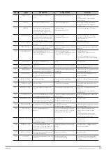
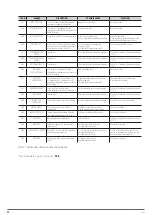
7.1. LEDS ON THE FRAME OF THE CONTROL PANEL.
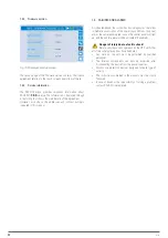
Fig. 55.
LED bar on the frame of the control panel.
LED
STATE
MEANING
LED 11
GREEN
AC line at the input of the
rectifier within tolerance
GREEN
Incorrect phase rotation (rapid
blinking)
GREEN
Unbalanced AC voltage (slow
blinking)
OFF
AC mains failure
LED 12
GREEN
BCB switch closed and batteries
charging
ORANGE
Batteries discharging or
performing test (rapid blinking)
ORANGE
BCB switch open (slow blinking)
RED
End of backup/Battery failure
LED 13
GREEN
Inverter voltage within tolerance
and static switch closed
ORANGE
Inverter overload or short-circuit
RED
Inverter critical alarm
OFF
Inverter off
LED 14
GREEN
AC bypass line within tolerance
RED
Incorrect phase rotation (rapid
blinking)
RED
AC bypass line out of tolerance/
Failure
LED 15
ORANGE
Scheduled maintenance required
(slow blinking)
ORANGE
Critical alarm (rapid blinking)
Tabla 15.
Meaning of LEDs on control panel frame.
Summary of Contents for SLC X-PERT Series
Page 1: ...SLC X PERT 80 400 kVA UNINTERRUPTIBLE POWER SUPPLIES UPS USER MANUAL...
Page 8: ...8 SALICRU Fig 3 Front view of the 400 kVA model...
Page 34: ...34 SALICRU Fig 42 Connection of three UPSs through the CAN bus for 400 kVA devices...
Page 60: ...60 SALICRU...
Page 61: ...61 X PERT UNINTERRUPTIBLE POWER SUPPLIES UPS USER MANUAL...

