53
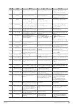
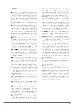
CODE
ALARM
DESCRIPTION
POSSIBLE CAUSE
SOLUTION
A18
MBCB CLOSED
The manual bypass circuit breaker is
closed.
Manual bypass circuit breaker closed.
Check status of manual bypass circuit
breaker.
Check functioning of circuit breaker’s
auxiliary contact.
A19
OCB OPEN
The output circuit breaker is open.
Output circuit breaker open.
Check status of output circuit breaker.
Check functioning of circuit breaker’s
auxiliary contact.
A20
OVERLOAD
The current sensor has detected an
overload at the output. If the alarm
persists, the thermal image protection
will be activated (alarm A21).
Overload at output.
Measurement circuit failure.
Check loads connected to UPS output.
A21
THERMAL IMAGE
The thermal image protection has been
activated after a prolonged overload in
the inverter. The inverter shuts down for
30 minutes and then restarts.
Overload at output.
Measurement circuit failure.
Check loads connected to UPS output.
If you need to restore the power of the
inverter immediately.
Restart the system.
A22
BYPASS SWITCH
The ‘Normal/Bypass’ selector has been
activated.
Maintenance tasks.
Check position of selector.
A23
EPO PRESSED
The system is disabled due to activation
of the emergency power off button.
Activation of emergency power off button
(local or remote).
Release emergency power off button and
reset alarm.
A24
HIGH TEMPERATURE
Heat sink temperature high in the
inverter bridge or tripping of the DC fuses
that protect the bridge.
Heat sink cooling fan failure.
Room or cooling air temperature too high.
Tripping of DC protection fuses.
Check fan operation.
Clean ventilation grilles and air filters,
if any.
Check air conditioning system (if any).
Check state of DC fuses at inverter bridge
input.
A25
INVERTER OFF
The inverter is disabled due to a
malfunction.
Several.
Reset the system.
A26
COMMUNICATION
ERROR
Internal error.
Microcontroller communication problems.
If the alarm persists, contact our Technical
Service and Support (T.S.S.).
A27
EEPROM ERROR
The controller has detected an error in
the parameters stored in the EEPROM.
Entering of incorrect parameters during
programming.
If the alarm persists, contact our Technical
Service and Support (T.S.S.).
A28
CRITICAL FAILURE
An alarm is activated which disables a
part of the UPS (rectifier, inverter, static
switch).
System fault.
Check which alarms present and follow
procedure indicated.
A29
MAINT. REQUIRED
Maintenance needed.
Time limit since last maintenance
exceeded.
Contact our Technical Service and Support
(T.S.S.).
A30
COMMON ALARM
Cumulative alarm.
At least one alarm activated.
Check which alarms present and follow
instructions.
A31
MBCB BUS CLOSED
The manual bypass circuit breaker is
closed.
Manual bypass circuit breaker closed.
Check status of manual bypass circuit
breaker.
Check functioning of circuit breaker’s
auxiliary contact.
A32
EPO BUS CLOSED
The system is disabled due to activation
of the emergency power off button.
Activation of emergency power off button
(local or remote).
Release emergency power off button and
reset alarm.
A33
ASYMMETRIC LOAD
The voltages measured in the DC
capacitors (positive and negative with
respect to the central point) are different.
Possible fault in measuring circuit.
Possible DC capacitor malfunction.
Reset the system.
A34
SERVICE REQUIRED
An inspection of the UPS is necessary.
Possible UPS malfunction.
Possible DC capacitor malfunction.
If the alarm persists, contact our Technical
Service and Support (T.S.S.).
A35
DIESEL MODE
The UPS is powered by a diesel
generator.
The auxiliary diesel generator activation
contact connected to the UPS is closed
and requires this operating mode.
Wait for the diesel generator to be
disabled once the voltage has been
restored.
Check the connection of the auxiliary
signal contact at the start of the diesel
generator in terminals XD1/XD2.
A36
RAPID DC SHUTDOWN
Inverter shutdown due to the intervention
of the protection sensor for unexpected
variations in DC voltage.
Battery failure.
Check batteries.
Reset the system.
A38
INVERTER-->LOAD
The load is powered by the inverter.
Alarm active in ‘ECO’ mode, where the
main supply comes from the bypass
network.
Temporary transfer due to lack of bypass
network.
Check the status of the bypass network
and any alarms present.
A39
INVERT. LOOP ERR.
The control cannot accurately regulate
the voltage of the inverter.
Regulation system fault.
Reset the system.
A40
SSI FAILURE
The system has detected a static switch
malfunction.
Possible load problems.
Static switch malfunction.
Check absorption of loads and possible
presence of continuous components on
AC current.
X-PERT
UNINTERRUPTIBLE POWER SUPPLIES (UPS)
USER MANUAL
Summary of Contents for SLC X-PERT Series
Page 1: ...SLC X PERT 80 400 kVA UNINTERRUPTIBLE POWER SUPPLIES UPS USER MANUAL...
Page 8: ...8 SALICRU Fig 3 Front view of the 400 kVA model...
Page 34: ...34 SALICRU Fig 42 Connection of three UPSs through the CAN bus for 400 kVA devices...
Page 60: ...60 SALICRU...
Page 61: ...61 X PERT UNINTERRUPTIBLE POWER SUPPLIES UPS USER MANUAL...

