55
8. MAINTENANCE, WARRANTY AND SERVICE.
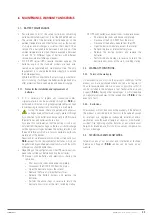
8.1. BATTERY MAINTENANCE.
•
Pay attention to all of the safety instructions concerning
batteries indicated in section 1.2.3 of the EK266*08 manual.
•
The service life of the batteries directly depends on the
ambient temperature and other factors such as the number
of charges and discharges, as well as their depth. Their
service life is designed to be between 3 and 5 years if the
ambient temperature to which they are exposed is between
10 and 20 °C. Different types of battery with different
service lives are available upon request.
•
SLC X-PERT series UPSs require minimum upkeep. The
batteries used in the standard models are lead acid,
sealed, valve regulated and maintenance free. The only
requirement is to charge the batteries regularly to extend
their life expectancy.
While the UPS is connected to the mains supply, whether or
not it is running, it will keep the batteries charged and also
offer protection from overcharging and deep discharge.
8.1.1. Notes for the installation and replacement of
batteries.
•
If it is necessary to replace any connection cables,
original materials can be purchased through our
T.S.S.
or
authorised distributors. Using inappropriate cables can lead
to overheating in connections, resulting in a fire hazard.
•
Inside the device, there are permanent dangerous
voltages even without mains supply present through
its connection to the batteries and especially in UPSs where
the electronics and batteries share a box.
Also take into consideration that the battery circuit is not
isolated from the input voltage, so there is a risk of discharge
with dangerous voltages between the battery terminals and
the earth terminal, which is in turn connected to earth (any
metal part of the device).
Repair and/or maintenance work must be carried out by our
T.S.S.
except for the replacement of batteries, which can
be performed by qualified personnel familiar with them. No
other person should handle them.
•
Depending on the configuration of the UPS, certain actions
need to be carried out before handling the batteries:
Devices with batteries and electronics sharing the
same box.
–
Shut down the loads and device completely.
–
Disconnect the SLC X-PERT from the mains.
–
Open the device to access the interior.
–
Remove the fuse or internal battery fuses.
–
Release the battery holders and replace the
batteries.
–
Perform the above steps in reverse to return the
device to how it was at the start, including startup.
UPS with batteries and electronics in separate boxes.
–
Shut down the loads and device completely.
–
Disconnect the SLC X-PERT from the mains.
–
Disconnect the battery module from the UPS.
–
Open the battery module to access the interior.
–
Remove the fuse or internal battery fuses.
–
Release the battery holders and replace the
batteries.
–
Perform the above steps in reverse to return the
device to how it was at the start, including startup.
8.2. WARRANTY CONDITIONS.
8.2.1. Terms of the warranty.
On our website, you will find the warranty conditions for the
product you have purchased where you can also register it.
You are recommended to do so as soon as possible so that it
can be included in the database of our Technical Service and
Support (
T.S.S.
). Among other advantages, it will streamline
any regulatory procedures for the intervention of
T.S.S.
in the
event of a fault.
8.2.2. Exclusions.
The company will not be bound by the warranty if the defect in
the product is considered to not exist or to have been caused
by improper use, negligence, inadequate installation and/or
verification, unauthorised attempts at repair or modification,
accident, fire, lightning or other hazards, or any other actions
beyond its intended use. Nor shall it cover any compensation
for loss or damage.
8.3. TECHNICAL SERVICES NETWORK.
Information about our national and international Technical
Service and Support (
T.S.S.
) centres can be found on our
website.
X-PERT
UNINTERRUPTIBLE POWER SUPPLIES (UPS)
USER MANUAL
Summary of Contents for SLC X-PERT Series
Page 1: ...SLC X PERT 80 400 kVA UNINTERRUPTIBLE POWER SUPPLIES UPS USER MANUAL...
Page 8: ...8 SALICRU Fig 3 Front view of the 400 kVA model...
Page 34: ...34 SALICRU Fig 42 Connection of three UPSs through the CAN bus for 400 kVA devices...
Page 60: ...60 SALICRU...
Page 61: ...61 X PERT UNINTERRUPTIBLE POWER SUPPLIES UPS USER MANUAL...

