9
reaching its end, the device will be automatically blocked,
leaving the loads unpowered.
Similarly, when mains voltage returns, the device
will start automatically.
4.
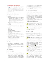
If an overload is detected, an audible alarm consisting of a long
beep will sound. To correct it, it is necessary to switch the
UPS off and disconnect the load that exceeds the rated
power of output sockets
3
with backup. wait 10 seconds.
Check that the fuse or circuit breaker of the line that sup-
plies the SPS is correct or set to ‘on’ and then restart the
UPS by pressing button
5
.
5.
To keep the battery fully charged, always leave the SPS plugged
into a live AC power outlet.
6.
If the UPS is stored or put away for a prolonged period of time,
protect it from dust, knocks, etc., and keep the battery fully
charged. Recharge the battery according to the time set in
Table 2 of the ek266*08 Safety Instructions document and
in correlation with the ambient temperature to which the
SPS.home is subject. That way, a longer battery life will
be ensured.
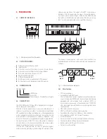
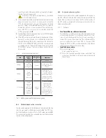
5.3.1.1. optical and audible indications.
LEd
Audible
alarm
Input breaker
2
conditions
on
not active
normal
normal
flashing
Slow
modulated
beep (every 30
sec)
normal
mains failure - The
UPS supplies power to
sockets 3.
flashing
Rapid
modulated
beep
(every 2 sec.)
normal
mains failure - The
UPS supplies power
to sockets 3. with low
battery voltage (end of
backup), the audible
alarm modulates every
2 sec
on / flashing
Rapid
modulated
beep
(every 0.5 sec)
for moderate
overload or
continuous for
excessive
normal /
Tripped
overload - Activated
by excessive load
connected to the
device’s output
sockets. Stop the UPS,
disconnect the load.
Activate the breaker if
necessary. Switch on
the UPS.
Tab. 1.
Optical and audible indications guide.
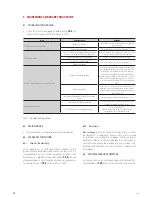
5.3.2. modem/telephone line connection.
Use the cable supplied for the telephone line to extend the line
from the wall socket to RJ45 input connector
8
of the SPS. Con-
nect the telephone, modem or fax to RJ45 output connector
9
.
This connection provides the connected device with protection
from possible voltage peaks.
5.3.3. communications connection.
Connect the communications cable supplied with the device to
the UPS’s USb port and the other end to the computer. with the
Power master software installed on the PC, both the status of
the UPS can be monitored and a shutdown/automatic start can
be performed remotely.
5.3.3.1. Software.
•
free Power Master software download.
Power master is a UPS monitoring software which provides
a user-friendly interface for monitoring and control. It fea-
tures an auto shutdown function for systems consisting of
several PCs in case of power failure. The software enables
users to monitor and control any UPS in the same LAn
through an RS232 or USb communications port, regardless
of how far away they are from each other.
•
Installation procedure:
go to the web page:
http://support.salicru.com
Select the required operating system and follow the
instructions described on the web page to download
the software.
SPS HOME
UnInTeRRUPTIbLe PoweR SUPPLy (UPS)
USER'S MANUAL


