- 35 -
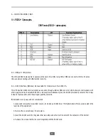
Pin 1. (UPS failure).
Pin 2. (General alarm).
Pin 7 . (Low battery).
Pin 8. (UPS On).
Pin 9. (Mains failure).
Pin 5. (Common).
Pin #
Description
I/O
1
UPS failure
Output
2
General alarm
Output
5
Common
Input
7
Low battery
Output
8
UPS On
Output
9
Mains failure
Output
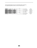
5
1
9
6
The following table and diagram, shows the pin-out of female DB9 connector and its function.
Do not apply values higher than 24 V DC and 1 A to the pins of the AS400 connector.
Summary of Contents for UNINTERRUPTIBLE POWER SUPPLY ADVANCE series
Page 1: ...EK459B01 User s manual installation and start up UNINTERRUPTIBLE POWER SUPPLY ADVANCE series...
Page 2: ...2...
Page 14: ...14 Examples to the LCD display If the mains supply exist If the mains supply do not exist...
Page 15: ...15 4 2 Introducing the LCD display 4 3 Audible alarm introduction polarity...
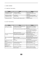
Page 36: ...36 9 TROUBLE SHOOTING 9 1 Audible Alarm Trouble Shooting 9 2 General Trouble Shooting...
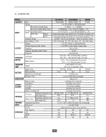
Page 37: ...37 10 SPECIFICATION Optocouplers 10 5 21 5 N A N A...
Page 39: ...39...
Page 40: ...salicru com 08460Palautordera Tel 3493 8482400 sat salicru com...

