33
English
2. Fix the rechargeable battery using the enclosed cable tie
NOTE
•
To ensure perfect operation, the rechargeable battery
must have been fully charged prior to insertion or
have been charged for 24 h in the switchgear.
•
The capacity of the rechargeable battery will fall if
temperatures drop. This reduces the running time of
the rechargeable battery.
6.
operation and function
This section contains all information on operating the switchgear
and how it functions.
PoTEnTIALLy fatal danger due to electrical voltage
When performing work on the uncovered switch-
gear, there is a risk of fatal electric shocks occur-
ring. All work on individual components must be
performed by a qualified electrician.
NOTE
Following a power supply interruption, the switch-
gear will automatically start up in the last operating
mode set!
6.1.
Controls
The switchgear is operated on the side control panel via 4 buttons.
The current operating state is indicated via 4 LEDs on the front
side.
6.1.1. Main switch
Network disconnection is via a main switch on the standard ver-
sion.
Position "0" = switchgear OFF
Position "1" = switchgear ON
NOTE
The main switch can be secured against unauthorized
activation/deactivation using a lock!
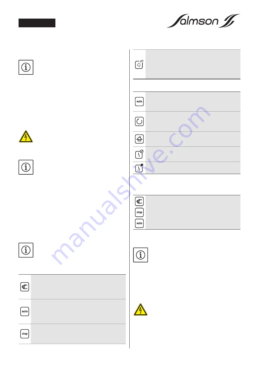
6.1.2. Buttons
Manual mode
By pressing this button, the pump is switched on inde-
pendently of the level control signal. The pump oper-
ates as long as the button is held down. This function is
intended for test mode.
Automatic mode
By pressing this button, automatic mode is activated.
The pump is activated/deactivated depending on the
level control signal. When the pump is deactivated, the
pump follow-up time is taken into account.
Stop
By pressing this button, automatic mode is deactivated
and the switchgear is set to stand-by mode. The pump is
not controlled depending on the level.
Buzzer oFF/reset
By pressing this button, the integrated buzzer is
switched off during a warning and the collective fault
signal relay (SSM) is deactivated.
When held down for longer, the fault shown is acknowl-
edged and control is reenabled.
6.1.3. LED indicators
Automatic mode (green)
LED flashing:
Switchgear is switched on but in stand-by
mode.
LED lights up:
Automatic mode is activated.
Pump operation (green)
LED flashing:
Pump running during the set follow-up
time.
LED lights up:
Pump running.
High water (red)
LED lights up:
High water level reached, high water alarm
has been triggered
"Excess current" fault (red)
LED flashing:
Switchgear is operating without any load.
LED lights up:
Rated current has been exceeded.
"Winding monitoring" fault (red)
LED lights up:
Temperature sensor has triggered.
6.2.
Button lock
To prevent erroneous or unauthorized activation of buttons, a lock
can be activated.
Activating/deactivating the button lock
Simultaneously pressing down the Manual mode, Stop
and Automatic mode buttons (for approx. 1 s), activates/
deactivates the buttons lock.
All LEDs light up for approx. 2 sec by way of confirmation.
If a button is pressed when the button lock is active, all LEDs also
light up for 2 secs.
NOTE
When the buttons lock is active, the buzzer can be
switched off and the collective fault signal relay de-
activated during an alarm signal with the Buzzer OFF/
Reset button. Faults cannot be acknowledged nor
can the control be released.
7.
Commissioning
PoTEnTIALLy fatal danger due to electrical voltage
Incorrect electrical connections can cause fatal
electric shocks. Electrical connections may only
be inspected by a qualified electrician approved by
the local energy supplier, in accordance with locally
applicable regulations.


