English
110
Salmson 05/2015
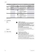
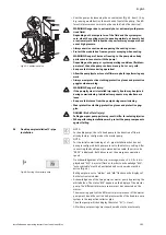
NOTE:
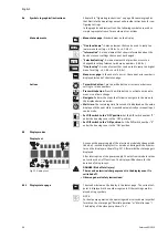
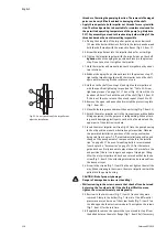
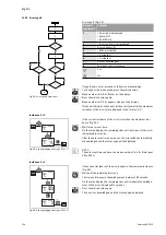
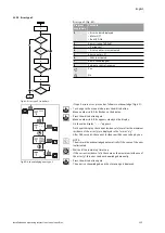
The procedure can be manually started later by selecting the menu
<5.1.2.0> (for information about navigation in the service menu, see
8.6.3 “Navigation” on page 99).
9.3
Adjusting the pump output
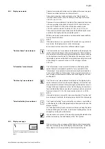
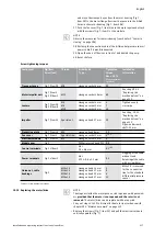
• The system was designed for a certain duty point (full load point, cal-
culated maximum heating capacity load). During commissioning, the
pump output (delivery head) is to be set according to the duty point
of the system.
• The factory setting does not correspond to the output required for
the system. It is determined with the help of the pump curve diagram
for the selected pump type (e.g. from data sheet).
NOTE:
The flow value shown on the IR-Monitor/IR-Stick display or output to
the building management system must not be used to control the
pump. This value is merely an indicator of general trends.
A flow value is not output on every type of pump.
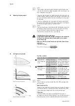
CAUTION! Risk of property damage!
An inadequate volume flow can lead to damage on the mechanical
shaft seal; the minimum volume flow depends on the rotation
speed of the pump.
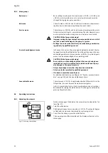
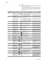
• Make sure that the volume flow does not go below the minimum
value Q
min
.
Calculation of Q
min
:
9.4
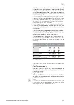
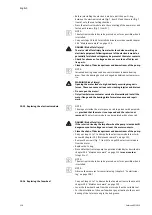
Setting the control mode
Δ
p-c/
Δ
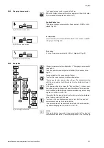
p-v control:
NOTE:
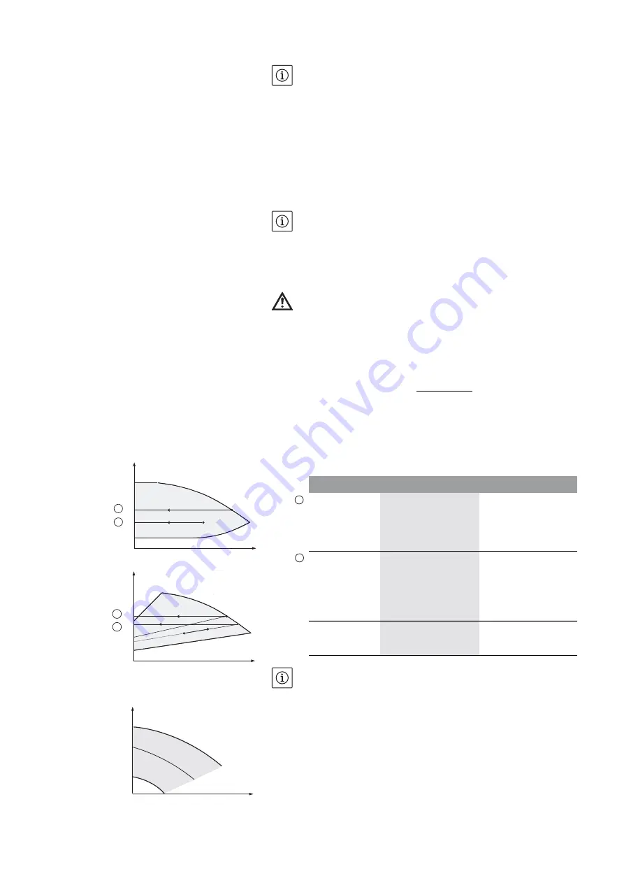
Alternatively, manual control mode (Fig. 48) or PID operating mode
can also be set.
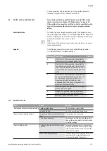
Manual control mode:
“Manual control” mode deactivates all other control modes. The speed
of the pump is kept to a constant value and set using the rotary knob.
The speed range is dependent on the motor and pump type.
PID control:
The PID controller in the pump is a standard PID controller, as
described in control technology literature. The controller compares a
measured process value to a predefined setpoint and attempts to
Q
min
= 10 % x Q
max
pump
x
Actual speed
Max. speed
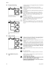
Fig. 47:
Δ
p-c/
Δ
p-v control
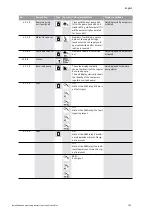
Q
s
H
max
H
H
s
H
min
H
s
1
2
Q
H
H
Q
H
max
H
s
H
min
H
s
1
2
Δ
p-c
Δ
p-v
Duty point on
maximum pump
curve
Starting at the duty
point, draw towards the
left. Read off setpoint
H
S
and set the pump to
this value.
Starting at the duty
point, draw towards the
left. Read off setpoint
H
S
and set the pump to
this value.
Duty point
within the con-
trol range
Starting at the duty
point, draw towards the
left. Read off setpoint
H
S
and set the pump to
this value.
Move to max. pump
curve along control
curve, then horizontally
to the left, read off set-
point H
S
and set the
pump to this value.
Setting range
H
min
, H
max
See pump curves
(e.g. on data sheet)
H
min
, H
max
See pump curves
(e.g. on data sheet)
1
2
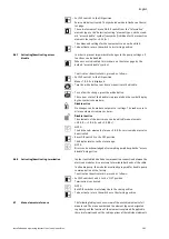
Fig. 48: Manual control mode
Q
H
H
Q
n
min
n
max
s
H
s
Summary of Contents for IXENS
Page 2: ......
Page 3: ......
Page 8: ...Fig 7 Ixens 13 20 22 21 15 16 17 18 19 14 13 12 11 10 9 8 7 4 3 2 1 6 5 20b 20a ...
Page 75: ...Français Notice de montage et de mise en service Ixens Ixens Bloc 67 ...
Page 137: ...English Installation and operating instructions Ixens Ixens Bloc 129 ...
Page 203: ...Italiano Istruzioni di montaggio uso e manutenzione Ixens Ixens Bloc 195 ...
Page 335: ......

