English
88
Salmson 05/2015
motor impeller unit from the pump housing (pay attention to the
previous dismantling and subsequent installation of the spacer).
• Transport eyes that have been installed at the motor housing are
not approved for the transport of the whole pump and not for sep-
arating or pulling out of the motor impeller unit from the pump
housing.
• Only lift the pump with approved lifting gear (e.g.
block and tackle,
crane, etc.; see chapter 3 “Transport and interim storage” on
page 71).
• When installing the pump, an axial minimum wall/roof clearance of
the motor’s fan cover of 400 mm is to be maintained.
NOTE:
Shut-off devices shall be installed upstream and downstream from
the pump in all cases, in order to avoid having to drain the entire sys-
tem when checking or renewing the pump.
CAUTION! Risk of property damage!
A volume flow going against or with the direction of flow (turbine
operation or generator operation) can cause irreparable damage to
the drive.
• A non-return valve shall be installed on the pressure side of each
pump.
NOTE:
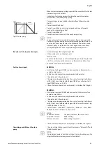
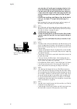
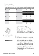
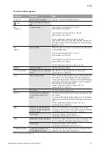
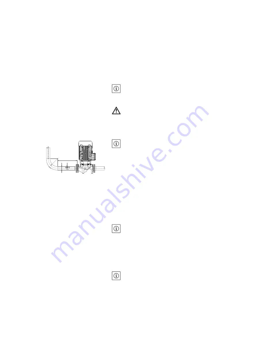
A settling section must be provided before and after the pump, in the
form of a straight pipe. The length of this settling section should be at
least 5 x DN of the pump flange (Fig. 26). This measure serves to avoid
flow cavitation.
• The pipes and pump must be free of mechanical stress when installed.
The pipes must be fixed in such a way that the pump is not supporting
the weight of the pipes.
• The direction of flow must correspond with the direction arrow on the
pump housing flange.
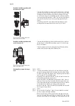
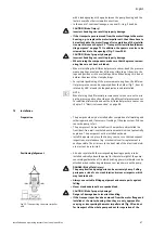
• The air vent valve at the lantern (Fig. 7, Item 19) always has to be
pointed upwards if the motor shaft is horizontal (Fig. 6/7). If the motor
shaft is vertical, any orientation is permitted.
• All installation positions except for “motor facing down” are allowed.
• The electronic module must not face downwards. If required, the
motor can be turned after loosening the hexagon head screws.
NOTE:
After loosening the hexagon head screws, the differential pressure
sensor is attached to the pressure measuring lines only. When turning
the motor housing, make sure that the pressure measuring lines are not
bent or kinked. Furthermore, while rotating the motor housing, it must
be ensured that the housing O-ring seal does not become damaged.
• For the permitted installation positions, see chapter 7.1 “Permitted
NOTE:
Ixens Bloc series monobloc pumps are to be mounted on a sufficiently
strong base or mounting brackets.
• The pump support foot for the Ixens Bloc must be firmly screwed onto
the foundation to ensure that the pump has a secure footing.
Fig. 26: Settling section before and after
the pump
r
5 x DN
d
s
r
⬇
2,5 · (d · 2s)
Summary of Contents for IXENS
Page 2: ......
Page 3: ......
Page 8: ...Fig 7 Ixens 13 20 22 21 15 16 17 18 19 14 13 12 11 10 9 8 7 4 3 2 1 6 5 20b 20a ...
Page 75: ...Français Notice de montage et de mise en service Ixens Ixens Bloc 67 ...
Page 137: ...English Installation and operating instructions Ixens Ixens Bloc 129 ...
Page 203: ...Italiano Istruzioni di montaggio uso e manutenzione Ixens Ixens Bloc 195 ...
Page 335: ......


