42
English
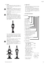
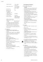
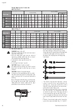
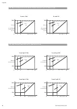
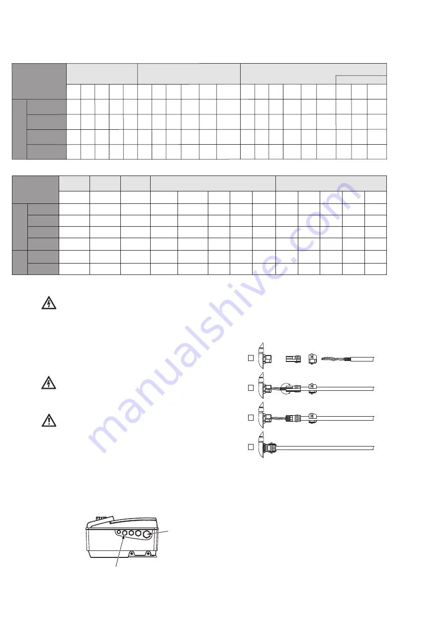
Principal dimensions and connection
MULTI-VE (Fig. 3)
NEXIS-VE (Fig. 3)
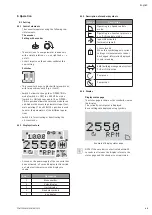
7.4 Electrical connections
DANGER!
Danger of death!
Inadequate installation and electrical connections
can be life-threatening.
• Electrical connections shall only be made by
approved specialised electricians and in compli-
ance with the applicable regulations.
• Accident prevention regulations must be
observed.
• Do not forget to connect to earth.
CAUTION!
Danger of mains overload!
An inadequate mains design can lead to system
failures and can lead to cable fires due to mains
overload.
CAUTION!
Danger of material damage!
A connection error would damage the converter.
The power cable shall never touch the pipe or the
pump ; make sure that it is protected against any
humidity.
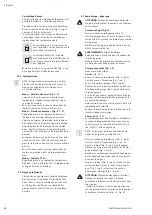
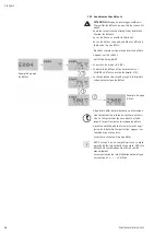
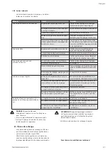
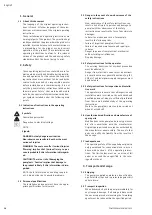
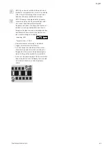
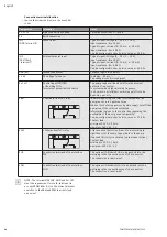
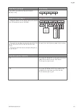
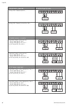
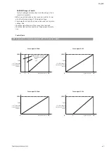
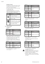
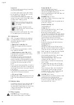
(Pos. a) The power cable (3 earth) must be
fed through the cable gland M25. Nonallocated
cable glands must remain sealed with the plugs
provided by the manufacturer (see below).
- (Pos. b) The sensor, external setpoint and
[aux.]/[ext.off] input cable must be necessarily
screened and must be inserted into the gland M12
or M16. The cable glands of the converter are
adapted to the assembly with a shielding braid
(see below).
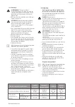
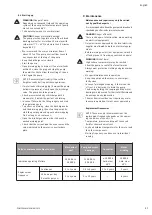
• The electric characteristics (frequency, voltage,
nominal current) of the motor-converter are
mentioned on the pump identification sticker
(item 19). Check that the motor-converter com-
plies with the mains supply used.
• The electric protection of the motor is integrated
into the converter. The parameters take into
account the characteristics of the pump and must
ensure its protection and the one of the motor.
• In case of impedance between earth and neutral
point, install a protection before motor-convert-
er.
• Provide a fuse-disconnecting switch (type gF) to
protect the mains installation (Fig. 1, 2, item 11).
a
b
١
٢
٣
٤
Pump type
Version PN16
Version PN25
A
B
C
D
E
F
G
ØH
D
E
F
G
ØH
6”
200/400
100
212
180
157
204
50
G1“ 2xM10 172
250
75
DN25 4xM12
600
100
212
180
157
204
50
G1“1/4 2xM10 172
250
75
DN32 4xM16
1000
130
255
215
190
250
80
G1“1/2 2xM12 190
280
80
DN40 4xM16
1600
130
255
215
190
250
90
G2“ 2xM12 190
300
90
DN50 4xM16
8”
2200
130
296
215
250
300
90
DN50 4xM16 250
300
90
DN50 4xM16
3600
170
296
240
250
320
105
DN65 4xM16 250
320
105
DN65 8xM16
Pump type
Version PN16
Version PN25
Victaulic
B
C
D
G ØT
A
E
F
S
ØU
R
A
E
F
ØS
ØU
R
E
F
R
6”
200
212 180 100 20 12 157 204 50
75 M10
G1”
172 250 75
85
14 DN25 210 50 Ø42,4
400
212 180 100 20 12 157 204 50
75 M10 G1”1/4 172 250 75 100 18 DN32 210 50 Ø42,4
800
252 215 130 20 12 187 250 80 100 M12 G1”1/2 187 280 80 110 18 DN40 261 80 Ø60,3
1600/6
252 215 130 20 12 187 250 90 100 M12
G2”
187 300 90 125 18 DN50 261 80 Ø60,3
POMPES SALMSON 06/2013
Summary of Contents for MULTI-VE Series
Page 2: ......
Page 3: ......
Page 5: ...5 11 7 6 1 13 3 2 7 100 mm Mini 200 mm Mini 100 mm Mini HA 2 BP Fig 1...
Page 6: ...8 9 12 5 11 2 3 2 7 7 4 4 6 13 10 ou or ou or 100 mm Mini HC Fig 2...
Page 8: ...Fig 4...
Page 9: ...2 14 1 Fig 5...
Page 10: ...10 17 16 ou or 15 Fig 6 10 ou or 17 15 16 Fig 7...
Page 11: ...17 16 15 Fig 8...
Page 12: ...19 18 Fig 9 Fig 10...
Page 13: ...Fig 11...

