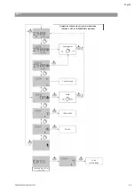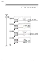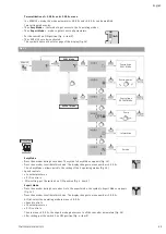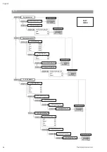
49
English
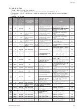
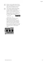
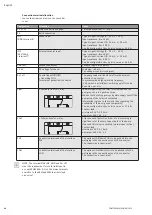
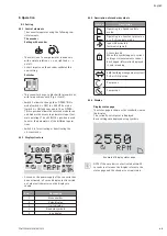
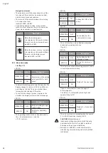
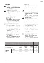
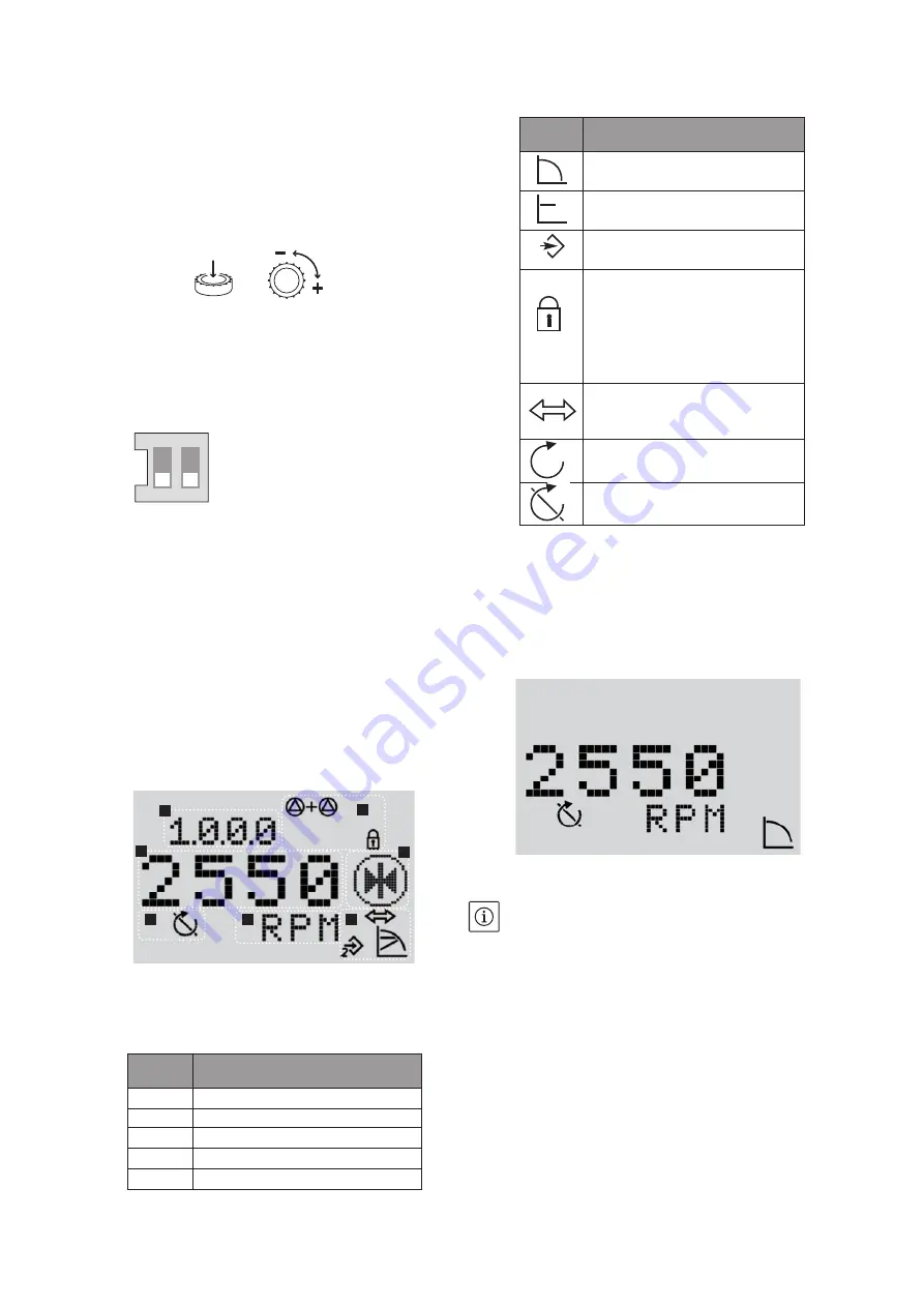
8.1.3 Description of standard symbols
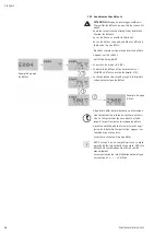
8.1.4 Display
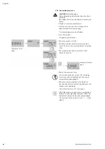
Display status page
• The status page is shown as the standard view on
the display.
The currently set setpoint is displayed.
Basic settings are displayed using symbols.
Example of display status page
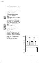
NOTE: If the encoder is not activated within 30
seconds in all menus, the display returns to the
status page and the change is not registered.
8. Operation
8.1 Setting
8.1.1 Control elements
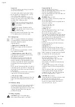
The converter operates using the following con-
trol elements:
The encoder
Setting with encoder
• The selection of a new parameter is done only
with a simple rotation, « + » on right and « - »
on left.
• A short impulse on the encoder validates this
new setting.
Switches
• This converter has got a block with two switches
with two positions each (Fig.4, item S):
• Switch 1 allows to change the « OPERATION »
mode [switch 1->OFF] to « SERVICE » mode
[switch 1->ON] and conversely. The « OPERA-
TION » position allows the selected mode to run
and hinders the access to parameters input (nor-
mal operating). The « SERVICE » position is used
to enter the parameters of the different opera-
tions.
• Switch 2 is for activating or deactivating the
« Access lock ».
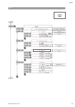
8.1.2 Display structure
• As soon as the power supply of the converter has
been activated, a 2 second display test is carried
out, where all characters on the display are
shown.
ON
1
2
1
2
3
5
4
4
4
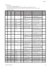
Pos.
Description
1
Menu number
2
Value display
3
Units display
4
Standard symbols
5
Icon display
Symbol
Description
Operating in « Speed control »
mode.
Operating in « Constant pressure »
or « P.I.D. control » mode.
Input IN2 activated
(external setpoint).
Access locked.
When this symbol appears, current
settings or measurements cannot
be changed. Information displayed
is only in reading.
BMS (building management system)
PLR or LON is active.
Pump runs.
Pump stops.
2
POMPES SALMSON 06/2013
Summary of Contents for MULTI-VE Series
Page 2: ......
Page 3: ......
Page 5: ...5 11 7 6 1 13 3 2 7 100 mm Mini 200 mm Mini 100 mm Mini HA 2 BP Fig 1...
Page 6: ...8 9 12 5 11 2 3 2 7 7 4 4 6 13 10 ou or ou or 100 mm Mini HC Fig 2...
Page 8: ...Fig 4...
Page 9: ...2 14 1 Fig 5...
Page 10: ...10 17 16 ou or 15 Fig 6 10 ou or 17 15 16 Fig 7...
Page 11: ...17 16 15 Fig 8...
Page 12: ...19 18 Fig 9 Fig 10...
Page 13: ...Fig 11...

