58
English
10. Faults, causes and remedies
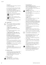
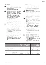
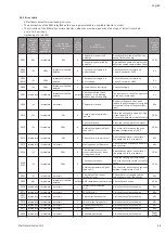
Faults should only be remedied by qualified person-
nel!
Observe the safety instructions, see <chapter 10>
Maintenance.
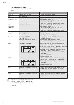
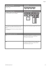
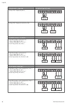
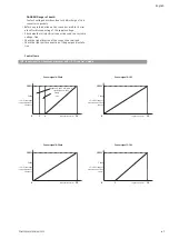
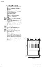
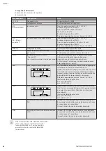
Relays
The converter is fitted with 2 output relays aimed for
an interface to centralized control.
ex.: control box, pumps control.
SBM
relay:
This relay can be configured in the « Service »
menu < 5.7.6.0 > in 3 operating states.
State: 1
« Available transfer » relay (normal operating for
this pump type).
The relay is activated when the pump runs or is
in a position to run.
When a first defect appears or by mains supply
cutoff (the pump stops), the relay is deactiveted.
Information is given to the control box, regarding
the availability of the pump, even temporarily.
State: 2
« Run transfer » relay.
The relay is activated when the pump runs.
State: 3
« Power on transfer » relay.
The relay is activated when the pump is con-
nected to the network.
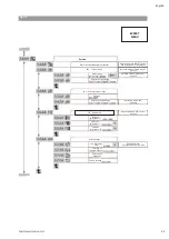
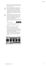
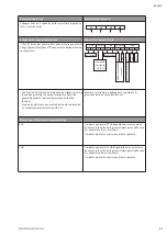
SSM
relay:
« Failures transfer » relay.
After a series of detection (from 1 to 6 according to
significance) of the same type of defect, the pump
stops and this relay is activated (up to manual action).
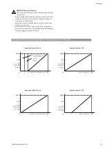
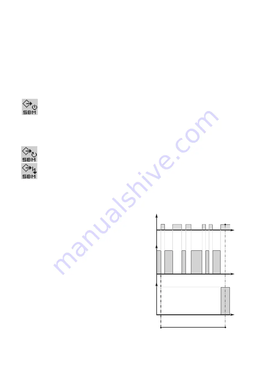
Example: 6 defects with a variable time limit on 24
sliding hours.
State of SBM relay is « Available transfer ».
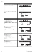
24H00 sliding
Defects
Active
relay
SBM
Rest
relay
Active
relay
SSM
Rest
relay
1
2
3
4 5
6
POMPES SALMSON 06/2013
Summary of Contents for MULTI-VE Series
Page 2: ......
Page 3: ......
Page 5: ...5 11 7 6 1 13 3 2 7 100 mm Mini 200 mm Mini 100 mm Mini HA 2 BP Fig 1...
Page 6: ...8 9 12 5 11 2 3 2 7 7 4 4 6 13 10 ou or ou or 100 mm Mini HC Fig 2...
Page 8: ...Fig 4...
Page 9: ...2 14 1 Fig 5...
Page 10: ...10 17 16 ou or 15 Fig 6 10 ou or 17 15 16 Fig 7...
Page 11: ...17 16 15 Fig 8...
Page 12: ...19 18 Fig 9 Fig 10...
Page 13: ...Fig 11...

