ENGLISH
8
3.3
SHORT
TERM
STORAGE
Leave
piping
connection
caps
fastened
to
keep
dirt
and
foreign
material
out
of
pump
casing
during
storage.
If
the
pump
will
not
be
used
immediately
after
delivery,
it
must
be
stored
in
a
temperate,
dry,
ventilated
location
and
away
from
vibrations.
Turn
the
pump
shaft
at
intervals
(every
month)
to
avoid
brinelling
of
the
bearings
and
the
seal
faces
from
sticking.
Close
protective
packing
when
done.
If
stored
as
described
above,
the
pump
can
be
stored
up
to
6
months.
Consult
SALMSON
for
preservative
procedure
when
a
longer
storage
period
is
required.
3.4
HANDLING
Depending
on
their
design
some
pumps
can
fall
over
before
they
are
definitively
fastened
to
the
floor.
Take
all
necessary
actions
to
ensure
that
no
‐
one
can
be
crushed
while
the
equipment
is
moved.
A
crane
must
be
used
to
lift
all
equipment
exceeding
25Kg.
Palettes,
crates
or
boxes
can
be
moved
or
unloaded
by
using
a
fork
‐
lift
truck
or
a
hoist
depending
on
lifting
devices
available
on
site.
Only
suitable
lifting
gear
and
load
carrying
equipment
with
valid
test
certificates
and
adequate
lifting
capacity
for
the
loads
involved
should
be
used
to
lift
and
carry
the
goods.
Only
authorized
personal
should
proceed
to
pump
transportation
and
they
must
respect
local
regulations.
Weight
of
goods
is
indicated
on
the
delivery
note.
Only
use
suitable
lifting
points
that
are
indicated
on
the
equipment
and
respect
hereafter
lifting
and
transportation
sketches.
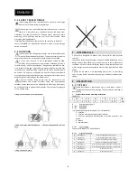
Pumps
should
never
be
lifted
directly
with
slings.
Hooks
must
be
used
and
placed
in
dedicated
lifting
holes.
Chose
proper
sling
length
or
use
a
lifting
beam.
Lifting
a
close
‐
coupled
or
a
biblock
pump
:
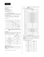
Lifting
a
pumpset
with
folded
base
:
Lifting
a
pumpset
with
cast
iron
base
:
Lifting
a
bareshaft
pump
:
4
INTENDED
USE
S
pumps
are
designed
to
handle
non
viscous
fluids
with
particles
content.
The
specific
casing
design
ensures
a
quick
and
reliable
selfpriming.
Pump
design
allows
a
long
lifetime
use,
even
when
run
in
the
harshest
duty
conditions.
Various
materials,
different
types
of
shaft
sealings
and
many
motor
configurations
are
available
to
match
major
industrial
and
OEM
needs.
S
pumps
can
be
used
in
most
demanding
process
lines
or
on
building
sites,
in
every
kind
of
industries
for
handling
of
effluents,
condensates,
sludge,
…
5
DESCRIPTION
5.1
TYPE
KEY
Pump
description
is
engraved
on
pump
name
plate.
It
gives
a
general
description
of
pump
design.
The
nameplate
is
attached
to
pump
casing.
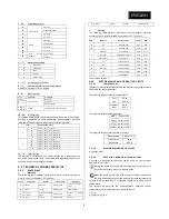
Product
information
according
description
:
EXAMPLE
:
S
40
F
A
R
‐
21
‐
T
11
/
2
K
‐
3B
1
2
3
4
5
6
7
8
9
10
S
:
Pump
product
line
:
S
1
:
(40)
Pump
size
2
:
(F)
Materials
(see
detail
of
pump
parts
in
chapter
«
5.2.1
Materials»)
‐
F
:
Cast
iron
‐
E
:
Cast
iron
casing
and
stainless
steel
impeller
‐
Z
:
Cast
iron
casing
and
stainless
steel
or
bronze
impeller
+
zinc
anode
‐
B
:
Bronze
‐
X
:
Stainless
steel
3
:
(A)
Shaft
sealing
See
details
in
chapter
«
5.2.1
Materials
»
4
:
(R)
Hydraulic
variants
R
Threaded
ports
With
self
regulated
greasing
cartridge
S
Flanged
ports
With
self
regulated
greasing
cartridge
T
Threaded
ports
Without
self
regulated
greasing
cartridge
U
Flanged
ports
Without
self
regulated
greasing
cartridge
C
Threaded
ports
With
self
regulated
greasing
cartridge
+
cutting
device
D
Flanged
ports
With
self
regulated
greasing
cartridge
+
cutting
device
F
Threaded
ports
With
external
Flushing
G
Flanged
ports
With
external
Flushing
Summary of Contents for S series
Page 2: ...S INSTALLATION ET MISE EN SERVICE N M S n 4071640 Ed 5 10 13 FRAN AIS...
Page 23: ...FRAN AIS 23...
Page 24: ...24...
Page 25: ...S INSTALLATION AND OPERATING INSTRUCTIONS N M S n 4071640 Ed 5 10 13 ENGLISH...
Page 26: ...2...
Page 48: ...24...

