background image


ENGLISH


13


quality


is


not


sufficient,


add


shims


between


ground


and


base


plate.


Distortion


on


base


plate


surface


should


be


limited


to


0,4mm/m


after


the


baseplate


is


definitively


fastened


to


foundations.


Coupling


alignment


is


checked


before


shipment


(pumps


and


motor


deliver


ed


on


a


common


baseplate)


If


coupling


is


not


correctly


aligned


after


installation


works


are


done


this


indicates


that


the


baseplate


has


become


twisted


and


leveling


should


be


corrected


by


re

shimming.


Even


if


foundation


works


have


been


done


with


care,


it


is


necessary


to


check


coupling


alignment


after


the


baseplate


is


definitively


secured


to


the


foundation.


7.1.2


ANCHORING


Chemical


anchoring


device


should


be


preferred


to


fasten


a


baseplate


on


an


existing


foundation.


Anchor


bolts


can


be


used


if


foundation


block


is


to


be


built.


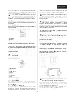
1


Anchor


bolt


2


Baseplate


3


Concrete


foundation


block


Folded


steel


fabricated


baseframes


will


be


grouted


to


insure


its


rigidity.


Using


of


shrink


free


grout


is


the


most


efficient.


Grouting


ensures


correct


positioning


of


the


baseframe


and


reduces


vibrations


transmission


to


civil


work.


Foundation


work


surface


preparation


and


leveling


of


baseframe


will


be


performed


in


the


state


of


the


art


and


should


be


done


before


grouting


of


the


baseplate.


Foundation


bolts


should


be


fully


tightened


only


after


the


grout


has


cured.


Installation


without


foundation


:


1


Intermediate


plate


2


Nut


3


Leveling


element


4


Foot


base


5


Washer


6


Fastening


nut


7


Washer


8


Baseplate


fastening


screw


7.1.3


POSITIONING


Pump


baseplate


(cast


iron


base


plate


or


fabricated


steel


baseframe)


should


be


installed


horizontally


to


ensure


bearings


lifetime


and


proper


flow


of


pumped


fluid.


7.1.4


COUPLING


ALIGNMENT


Pumpsets


assembled


with


a


flexible


coupling


(except


pump


variants


equipped


with


a


IEC


lantern)


must


be


aligned


after


the


baseframe


has


been


definitively


fastened


to


the


foundation.


Use


low


thickness


shims


(0,2


to


1


mm)


to


modify


coupling


alignment.


Adjust


the


motor


height


first.


Sometimes


it


is


necessary


to


add


shims


under


pump


feet


too.


Aligment


of


coupling


should


be


performed


with


particular


care


when


the


pumpset


is


installed


in


an


hazardous


area.


Correct


alignment


will


avoid


abnormal


increasing


of


the


pump


and


motor


ball


bearings


temperature.


Thermal


expansion


:


the


pump


and


motor


will


normally


have


to


be


aligned


at


ambient


temperature


with


an


allowance


for


thermal


expansion


at


operating


temperature.


In


pump


installation


involving


high


liquid


temperatures,


alignment


should


be


checked


again


when


operating


temperature


is


reached


(pump


and


piping).


Alignment


quality


should


be


checked


just


after


machine


shut


down.


Pump


and


driver


must


be


isolated


electrically


before


alignment


operations


are


performed.


Pump


and


motor


were


aligned


before


dispatch.


If


it


is


necessary


to


use


very


thick


shims


to


adjust


coupling


alignment


on


site


this


means


that


the


baseplate


is


twisted.


Leveling


has


to


be


modified.


Checking


the


coupling


alignment


:


Check


distance


between


the


two


half


couplings.


Check


radial


and


axial


deviation.


Several


types


of


flexible


couplings


can


be


used.


Refer


to


coupling


operating


instructions


to


know


adjustment


values


and


misalignment


limits.


Several


methods


can


be


used


to


make


coupling


alignment.


Choice


of


a


method


will


depend


on


the


type


of


equipments


available


on


site.


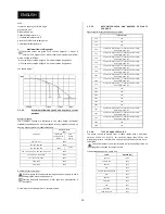
Two


operating


methods


are


briefly


described


hereafter.


They


can


be


used


if


basic


metrology


equipments


are


available


:


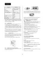
Using


a


straight

edge


and


a


caliper


:


Using


a


dial


gauge


:


When


checking


parallel


alignment,


the


total


indicator


read

out


shown


is


twice


the


value


of


the


actual


shaft


displacement.


Align


in


the


vertical


plane


first,


then


horizontally


by


moving


the


motor.


Lifetime


of


ball


bearing


and


coupling


flexible


part


as


well


as


pumpset


noise


level


will


depend


on


the


alignment


quality.


Coupling


alignment


is


not


necessary


when


a


IEC


adaptation


lantern


is


used.


Both


motor


and


pumps


shaft


are


aligned


by


construction.


Summary of Contents for S series

Page 1: ...S INSTALLATION ET MISE EN SERVICE INSTALLATION AND OPERATING INSTRUCTIONS N M S n 4071640 Ed 5 10 13 FRAN AIS ENGLISH...

Page 2: ...S INSTALLATION ET MISE EN SERVICE N M S n 4071640 Ed 5 10 13 FRAN AIS...

Page 3: ...2 9 2 Temp ratures du fluide 6 2 9 3 Risque d accumulation de m langes explosifs 7 2 9 4 Risque de fuites 7 2 9 5 Groupe complet 7 2 9 6 Groupe livr sans moteur sans instrumentation 7 2 9 7 Protecteu...

Page 4: ...r les effectuer apr s d marrage 16 8 5 Mise hors service 16 8 6 Temps d amor age 16 9 Maintenance 17 9 1 G n ralit s 17 9 2 Programme d entretien et inspections p riodiques 17 9 2 1 Lubrification 17 9...

Page 5: ...ique m canique chimique thermique etc Dommages mat riels Perte de la protection anti d flagrante Risque de pollution de l environnement 2 4 CONSIGNES DE S CURIT 2 4 1 CONSIGNES DE SECURITE POUR L UTIL...

Page 6: ...r e sans moteur certificat CE d incorporation fourni avec la pompe il est de la responsabilit de l int grateur de respecter toutes les r gles en vigueur pour pouvoir certifier son quipement CE La cert...

Page 7: ...tection du moteur lectrique 2 9 6 GROUPE LIVR SANS MOTEUR SANS INSTRUMENTATION Lorsqu un groupe moto pompe fait l objet d une livraison partielle moteur accouplement carter ou capteur non fourni un ce...

Page 8: ...Prendre les pr cautions n cessaires pour viter tout risque d crasement pendant le d placement des quipements Utiliser un moyen de levage m canique pour soulever tout mat riel dont le poids d passe 25...

Page 9: ...T4 3 A ZONE 2 CAT 3 II 3G T x B ZONE 2 CAT 3 II 3G EEx d IIB T4 C ZONE 2 CAT 3 II 3G EEx d IIC T4 D ZONE 2 CAT 3 II 3G EEx de IIB T4 E ZONE 2 CAT 3 II 3G EEx de IIC T4 11 X Construction sp ciale Si vo...

Page 10: ...2400 S91 S121 S161 S201 2000 S180 S230 1600 S170 S220 1200 Nombre de d marrages par heure Attendre l arr t complet du moteur avant de lancer un nouveau d marrage sous peine d endommager moteur et pom...

Page 11: ...0 88 81 98 S105 1450 83 67 73 S108 2900 86 84 84 S120 1450 78 74 78 S150 1450 84 74 89 S160 1450 81 75 80 S170 950 83 76 77 Niveau sonore indicatif exprim en dBA LpA 1 m 5 2 5 POSITION DES BRIDES L ax...

Page 12: ...e se visse directement sur le fond porte grain 7 MONTAGE ET RACCORDEMENT ELECTRIQUE 7 1 IMPLANTATION Les quipements devant fonctionner en zone dangereuse classifi e ATEX doivent tre certifi s et r pon...

Page 13: ...rature anormale des paliers de la pompe et du moteur TEMPERATURE l alignement initial entre la pompe et le moteur est r alis e temp rature ambiante et moteur froid Si la pompe est utilis e sur un flu...

Page 14: ...alisation de chasse d air est identifi e ATEX Si un clapet anti retour est install au refoulement de la pompe il sera n cessaire d installer un vent ou une purge avec retour vers le r servoir ou la cu...

Page 15: ...NPSHr de la pompe vitesse minimum est toujours amplement inf rieur au NPSHd de l installation M canique La vitesse minimale ne doit pas descendre en dessous de 40 de la vitesse nominale de la pompe p...

Page 16: ...ire fonctionner la pompe dans ces conditions au del de quelques secondes Apr s l arr t complet de la pompe toutes les vannes seront ferm es Si la pompe est quip e d un quench r chauffage flushing lubr...

Page 17: ...iv s Les abords du groupe motopompe doivent tre nettoy s 9 2 PROGRAMME D ENTRETIEN ET INSPECTIONS P RIODIQUES Pour garantir le bon fonctionnement de l quipement et minimiser les risques d al as pendan...

Page 18: ...9 3 1 2 DEMONTAGE DU FOND PORTE GRAIN Version monobloc 1 D visser les vis 6570 de fixation du moteur 8020 2 D poser le fond porte grain 4211 Version palier 1 D visser les vis 6570 de fixation du porte...

Page 19: ...semi lastique Le moteur peut tre quip de paliers roulements billes lubrifi s vie 2Z comme de paliers quip s de graisseurs manuels Les graisseurs sont alors visibles au droit des paliers et les quantit...

Page 20: ...dans la boite bornes du moteur Fuite du corps de pompe de l tanch it d arbre ou de la conduite d aspiration Remplacer le joint de corps Contr ler l tanch it d arbre Contr ler l tat des joints des bri...

Page 21: ...on de votre commande 12 1 1 PLAN EN COUPE 12 1 2 NOMENCLATURE Rep re D signation 1100 Volute 1139 Bride aspiration 1221 Fond de corps Inox 1230 Trappe de visite 1381 Bride de refoulement 1915 Plaque d...

Page 22: ...age automatique certaines options ne concernent peut tre pas votre pompe Notre Service Pi ces de Rechange peut confirmer la nomenclature de la pompe gr ce au num ro de s rie disponible sur la plaque s...

Page 23: ...FRAN AIS 23...

Page 24: ...24...

Page 25: ...S INSTALLATION AND OPERATING INSTRUCTIONS N M S n 4071640 Ed 5 10 13 ENGLISH...

Page 26: ...2...

Page 27: ...ve atmosphere 6 2 9 1 Specific marking instructions for ATEX 6 2 9 2 Fluid Temperature 6 2 9 3 Build up of explosive mixture 7 2 9 4 Preventing leakage 7 2 9 5 Complete unit 7 2 9 6 Pump unit delivere...

Page 28: ...3 Start up 16 8 4 Running checks 16 8 5 Shutdown 16 8 6 Priming time 16 9 MAINTENANCE 17 9 1 General information 17 9 2 Maintenance and periodic inspections schedule 17 9 2 1 Lubrication 18 9 2 2 Var...

Page 29: ...cal and chemical thermal risks Property damages Loss of ex proof protection Risk of environmental pollution 2 4 SAFETY INSTRUCTIONS 2 4 1 SAFETY INSTRUCTIONS FOR THE OPERATOR OPERATION ON THE PUMP SET...

Page 30: ...sponsibility He will ensure that aIl specifications listed in this instructions are fully respected 2 9 SECURITY INSTRUCTIONS TO BE APPLIED ON EQUIPMENTS USED IN POTENTIALLY EXPLOSIVE ATMOSPHERE This...

Page 31: ...ents for the complete machine 2 9 7 COUPLING GUARD The coupling guard used in a potentially ATEX atmosphere shall meet following requirements Consist of non sparking material e g brass Must be made of...

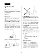
Page 32: ...proper sling length or use a lifting beam Lifting a close coupled or a biblock pump Lifting a pumpset with folded base Lifting a pumpset with cast iron base Lifting a bareshaft pump 4 INTENDED USE S p...

Page 33: ...l E Cast iron SS 316 Stainless Steel Stainless Steel Z Cast iron zinc anode Bronze or stainless steel Stainless Steel Bronze or stainless steel B Bronze Bronze Stainless Steel Bronze X SS 316 SS 316 S...

Page 34: ...er than QBEP or if abrasive content is high choose bigger pump size S 63 If flow much higher than QBEP or if abrasive content is high choose bigger pump size S 68 If flow much higher than QBEP or if a...

Page 35: ...0 2900 88 81 98 S105 1450 83 67 73 S108 2900 86 84 84 S120 1450 78 74 78 S150 1450 84 74 89 S160 1450 81 75 80 S170 950 83 76 77 Indicative noise level given in dBA LpA at 1 m 5 2 5 CONNECTIONS Suctio...

Page 36: ...Weight of the full lubricator is app 190g and empty app 75g The dispensed product is a special water repellent grease When it is switched on the integrated electronic device regulates grease dispersi...

Page 37: ...the foundation Use low thickness shims 0 2 to 1 mm to modify coupling alignment Adjust the motor height first Sometimes it is necessary to add shims under pump feet too Aligment of coupling should be...

Page 38: ...tion flange level When suction pipe is full of liquid the pump is acting like a standard centrifugal pump Priming time will increase if a larger pipe diameter is used or if pipe length is increased An...

Page 39: ...le and known The electric motor that is supplied with the pump may be connected under conditions to a VSD Variable speed will be used to reach pump required duty point on site To ensure a reliable use...

Page 40: ...onsumption on each phase of the motor Check calibration of motor protections Check temperature of ball bearings on bearing housing surface Check flexible coupling alignment after several pump starts o...

Page 41: ...e available near the pump The maintenance crew should be informed about the risks linked to the use of the pump and to the pumped fluids before they can start working on the equipment dangerous produc...

Page 42: ...ign was chosen a sacrificial anode is fastened onto the impeller inspection cover Cover fitted with 1 anode Cover fitted with 2 anodes The loss of the anode material should be checked after 1 month 3...

Page 43: ...ng the shaft or the bearing 3 Slide the assembly in the bearing housing 4 Install bearing cover and tighten fastening screws 9 3 2 2 ASSEMBLY OF MECHANICAL SEAL Assembly is performed in the reverse st...

Page 44: ...ket spanner up to M 48 Allen keys up to 10 mm Range of screwdrivers Soft mallet If maintenance work must be performed in an ATEX classified area then make sure that use of all necessary tools are auth...

Page 45: ...on pump casing gaskets on shaft sealing or on suction piping Replace casing seal s Check shaft sealing Check the state of the flanges seals Pump is not lifting liquid Air leaks into pump through mech...

Page 46: ...drawing and bill of material is available upon request The demand should be sent to our Spare parts Dpt and should mention pump description and serial number Data are engraved on the pump name plate a...

Page 47: ...f packing rings Set of bearing bracket ball bearings Set of shaft bearing Set of motor ball bearings for frame size 90 Complete set of seals and gaskets Coupling elastic part s Automatic greasing cart...

Page 48: ...24...
Page 49: ...OUJOURS DISPONIBLE SUR SITE Ce produit a t fabriqu sur un site certifi ISO 14 001 respectueux de l environnement Ce produit est compos de mat riaux en tr s grande partie recyclable En fin de vie le fa...

Reviews: