5.3 Electrical connections
The electrical connections and checks must be made by a
qualified electrician and comply with applicable local
standards.
Refer to the motor data plate for its electrical characteristics
(frequency, voltage, nominal current).
Three-phase motors
The motors must be protected by a circuit-breaker set to the current
mentioned on the name plate of the motor.
Provide a fuse disconnecting switch (type
aM
) to protect the mains
supply.
Single-phase motors
The single-phase motors have an integrated thermal protection.
Line power
A supply cable with an adequate ample external diameter should
be used to protect against damp and to secure the mains lead
cleat of the cable gland. (e.g. H05RN-F 3/4 G 1,5). A damaged
cable must be replaced by a cable available from the supplier or
his after-sales.
•
THREE-PHASE
: 4 conductors (3 earth)
•
TWO-PHASE
:
3 conductors (2 earth)
The electric connections should be made as shown by the diagrams
inside the cover of the motor terminal box (or
see FIG. 2
).
DO NOT FORGET TO CONNECT THE EARTH.
A connection error would damage the motor. The power
cable must never touch the pipe or the pump; make sure
that it is away from any moisture.
6. STARTING UP
6.1 Filling, degassing
Never operate the pump dry, even briefly.
Pump under pressure (see FIG. 4)
- Close the discharge valve (
3
).
- Unscrew the filling plug (
5
).
- Open the suction valve progressively (
2
) and completely fill the
pump.
- Screw the filling plug back in only after water flows out and all air
has been eliminated.
Pump in suction (see FIG. 3)
- Be sure that all accessories connected to the pump delivery are
opened (cocks, valves, sprinkling sprays).
- Open the discharge valve (
3
).
- Open the suction valve (
2
).
- Unscrew the draining plug (
5
) on the pump casing.
- Put a funnel into the port and slowly and completely fill the pump.
- Screw the plug back in.
- Keep the delivery pipe in a vertical position on a height of at least
500 mm up to priming of the pump, when the suction head is
higher than 7 m.
6.2 Check of direction of rotation of three-phase motor
Power up the motor by briefly pressing the circuit-breaker and
check that it turns in the direction indicated by the arrow on the
pump lantern.
In the contrary case cross the two phase wires on the motor terminal
block or on the motor protection relay.
NOTE
:
The single-phase motors are designed to turn in the right direction in
all cases.
6.3 Starting up
The pump must not be operated in a no-flow
condition (discharge valve closed) for more than
10 minutes.
We recommend to ensure a minimum flow of about or higher than
10% of the nominal flow of the pump to avoid the formation of a
vapour lock at the top of the pump.
- Open the discharge valve.
- Start the pump.
- Close then open again the discharge valve to come back safety
on flow-head curve with priming valve closed.
- Check that the current input does not exceed the value indicated
on the motor data plate.
7. SERVICING
No special maintenance during operation.
Keep the pump and the motor perfectly clean.
For a prolonged shutdown, if there is no risk of frost, it is best not to
drain the pump.
To avoid any blocking of the shaft and the hydraulic system, in frosty
periods, empty the pump by removing the plug (
6
) and the filling
plug (
5
).
- Screw the 2 plugs back in, without tightening them.
Fill the pump before any next use.
Replacement frequencies
These are no more than recommendations; the actual replacement
frequencies will depend on pump operating conditions, namely:
• Temperature, pressure of the conveyed fluid and starting
frequency for the mechanical seal.
• Load, ambient temperature and starting frequency for the motor
and the other components.
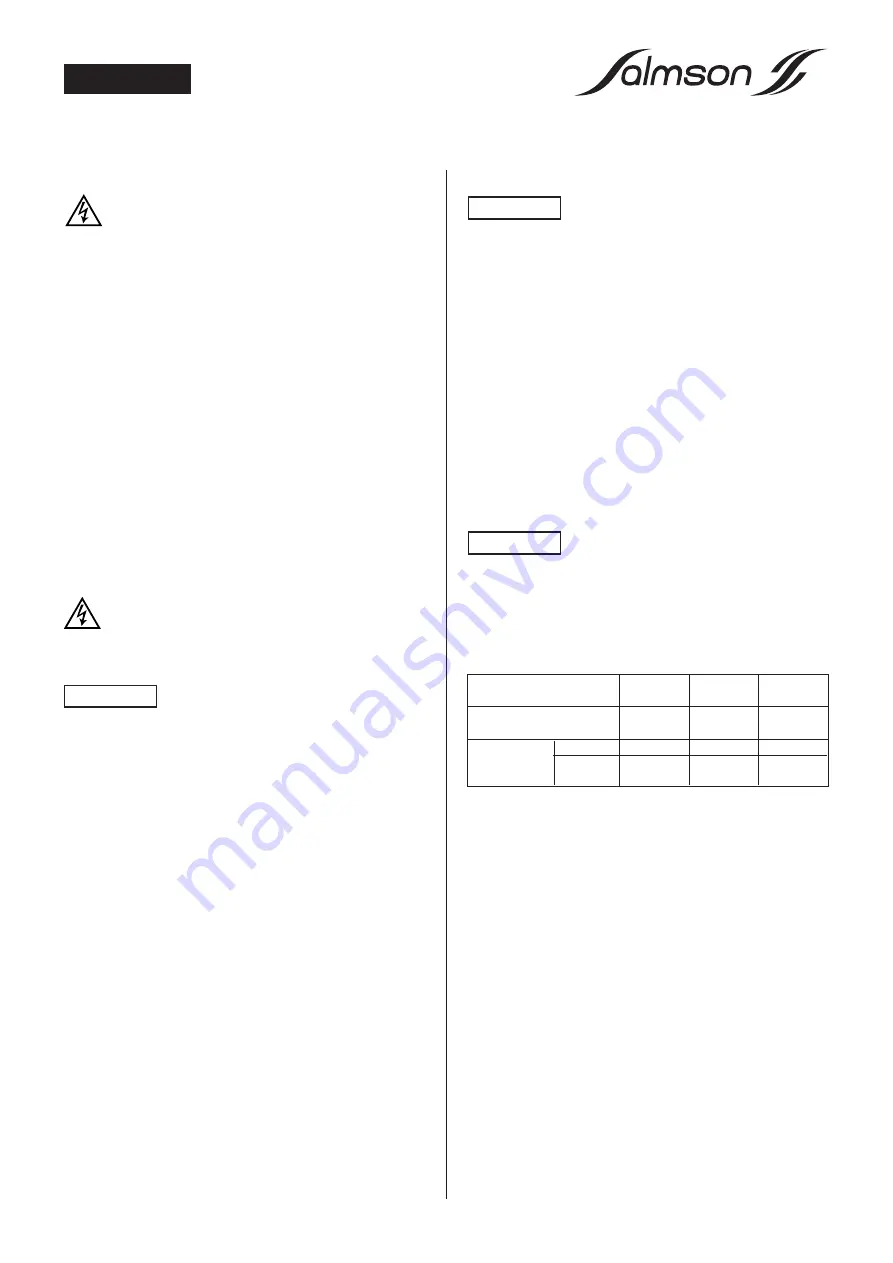
Parts or component
Mechanical
Motor
Motor
subject to wear
seal
bearings
winding
Operating
4 000 to
4 000 to
25 000 h
life (average)
8 000 h
8 000 h
max. amb.+ 40°C
Replacement duty
6 mths to 1 year
6 mths to 1 year
3 years
frequency
15h/day
in service
9 mths/yr
1 to 2 years
1 to 2 years
6 years
Motors without grease fitting
The bearings are greased for life and so need no lubrication.
Mechanical seal
The mechanical seal needs no servicing in operation.
It must never be allowed to operate dry.
ATTENTION !
ATTENTION !
ATTENTION !
10
ENGLISH
Summary of Contents for SPRINGSON
Page 2: ...2...
Page 3: ...3...
Page 4: ...4 Y HIGH VOLTAGE LOW 3 1 1 1 7 2 5 4 3 7 6 200 mm MIN 500 mm MIN 100 mm MIN HA FIG 2 FIG 1...
Page 5: ...5 7 2 12 10 4 11 9 8 o or HC 2 5 4 3 7 3 PH 6 5 FIG 4 FIG 3...
Page 18: ...18 NOTES...
Page 19: ...19 NOTES...


