background image


CONTENT


. SPECIFICATIONS. ………………………………………………    P1 

. KEY FUNCTION.  ………………………………………………  P3 

. CALIBRATION. ………………………………….………………    P6 

. Examination mode…………………………………………………    P9 

. SETUP MODE. ……………………………………………………    P11 

. Details of RS232 Communication………………………………...    P18 

. Calibration resolution, division and capacity …..………………… P21 

. Meaning of some displayed symbols. …………………………….    P24


. Direction of indicator with bracket. ………………………. ……… P25 

.Key Definition summary: ………………………. ………………...… P26   

.Parameters setting summary: ………………………………... ...…    P27 

Operation Manual


Thank you for purchasing the 140 indicator. Please read all operating 

instructions carefully before use and keep the following points in mind: 
* Avoid lengthy exposure to extreme heat or cold, your scale works best when 
operated at normal room temperature. Always allow the scale to acclimate to a 
normal room temperature before use   
* Allow sufficient warm up time. Turn the scale on and wait for a few minutes if 
possible, to give the internal components a chance to stabilize before weighing. 
* These electronic scales are precision instruments. Do not operate near an in-use 
cell phone, radio, computer or other electronic device. These devices emit RF and 
can cause unstable scale readings. If your scale ever performs poorly, try moving 
the scale to a different room or location.   
* Avoid using in condition of heavy vibration and airflow. 
* Read the weight reading in short time after loading. The output signature of load 
cell and A/D may be little influenced after weighing for a long time.     


.

 SPECIFICATIONS: 


 ·

SCALE INDICATOR


1. Input signal range: 0

mV ~ +30mV


2. Sensitivity: >0.2uV/grad 
3. Internal Resolution: Approximately 520,000 counts   
4. Display Resolution: can be selected between 500-100,000   
5. System Linearity: within 0.01% of FS 
6. Loadcell excitation Voltage: +4.4 VDC (MAX current: 55mA) 
    MAX 4- 350 ohm loadcells. “Only 140 indicator manual” 
7. Calibration Method: Software calibration with long-term storage in 

EEPROM. 


·

SERIAL COMMUNICATIONS: 

1. Mode: Full duplex or only output mode can be selected 
2. Baud rate: 1200, 2400, 4800, 9600, or 19200 bps 
3. Data format:    8NO, 7E1, 7O1 

              8data bits, non parity, 1 stop bit 


    7data bits, 1bit even or odd parity, 1 stop bit 

4. Protocol: 7selected protocol (include the one compatible with NCI   

Summary of Contents for LPS-400

Page 1: ...LPS 400 SCALE Operation Manual Contents subject to change without notice Version 1 0 2006 07 26...

Page 2: ...aux appareils num riques de la Classe A prescrites dans le R glement sur le brouillage radio lectrique edict par le minist re des Communications du Canada Warnings Electrical installation For your pro...

Page 3: ...radio computer or other electronic device These devices emit RF and can cause unstable scale readings If your scale ever performs poorly try moving the scale to a different room or location Avoid usi...

Page 4: ...below 4 7V and you should replace batteries immediately 2 AC Adapter 6VDC 500mA with central negative 3 Work current 25mA when voltage in 5Vdc 8Vdc and not include load cell s consumption OPERATION T...

Page 5: ...b oz Note The weighing units that can be used are restricted by display division and calibration weight unit restricted by P8 P9 and P10 For example if the calibration unit is kg calibration display r...

Page 6: ...r input working voltage to be displayed The working voltage range is 4 8V 8V If the voltage is not within range it may damage the indicator Voltage value is shown like this U x xx and its unit is V 3...

Page 7: ...le will be calibrated on second calibration point The default standard weight is 50 FS and at the same you can press ON OFF ZERO to exit the calibration mode Or load 12 5 100 FS weight and use PRINT H...

Page 8: ...the A D data for loaded weight If the ADC increase for full capacity is NFS the power on zero range is set to Zp FS P12 setting and zero key range is set to Zk FS P13 setting Then proper ADC data of z...

Page 9: ...thin the setting range 3 50d the weight reading will remain unchangeable 11 5 4 P4 x RS232 mode setting x 0 No RS232 function It will not transmit or receive any data although the scale is with RS232...

Page 10: ...cimal digits x10 3 x 4 four decimal digits x10 4 x 5 no decimal point x10 1 5 10 P10 x Calibration unit x 0 kg as calibration unit x 1 lb as calibration unit As per the setting of P8 P9 and P10 follow...

Page 11: ...zero point CAL P0 5 FS x 3 the range is set to calibration zero point CAL P0 10 FS x 4 the range is set to calibration zero point CAL P0 20 FS x 5 the range is set to calibration zero point CAL P0 50...

Page 12: ...1d 9d If the variety of weight reading is within the setting range continuously for several times the scale is recognized as stable The normal setting is 1d 3d 5 19 P19 x Overload range that can be di...

Page 13: ...u2 CR LF H1H2H3 CR ETX zero point error Note If the weight unit is lb oz U1U2 oz in above item 19 LF p w1w2w3w4w5w6 dp w7u1u2 CR LF H1H2H3 CR ETX Scale is stable and the current weight unit is kg or l...

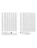
Page 14: ...400 24000 2500 0 2500 2 500 25 00 250 0 2500 25000 3000 0 30000 3 000 30 00 300 0 3000 30000 3500 0 3500 3 500 35 00 350 0 3500 35000 4000 0 4000 4 000 40 00 400 0 4000 40000 5000 0 5000 5 000 50 00 5...

Page 15: ...500 25 00 250 0 2500 25000 600 0 3000 3 000 30 00 300 0 3000 30000 23 750 0 3750 3 750 37 50 375 0 3750 37500 800 0 4000 4 000 40 00 400 0 4000 40000 1000 0 5000 5 000 50 00 500 0 5000 50000 1200 0 6...

Page 16: ...ition summary KEY MODE DEFINITION Normal weighing mode Enter or exit HOLD mode output the data as per P4 P5 P6 setting Setup mode Calibration mode Shift the flashed position from right to left HOLD PR...

Page 17: ...00 31 7 Resolution select 500 600 750 800 1000 1200 1500 2000 2400 2500 3000 3500 4000 5000 6000 7000 7500 8000 10000 12000 15000 20000 25000 30000 35000 40000 50000 60000 70000 75000 80000 100000 P8...

Page 18: ...2 3 2 Data filter intensity 0 very weak 1 weak 2 middle 3 strong P18 x 0 1 9 1 Check weight stability range 0 0 5d 1 1d 2 1 5d 3 2d 4 3d 5 4d 6 5d 7 6d 8 7d 9 8d P19 x 0 1 9 3 Overload limit range 0...

Reviews: