background image

14

NAME/CODE

DESCRIPTION

CODE/VALUE

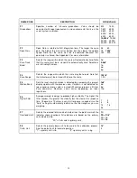
F9

Display

Divisions

Determines  the  desired  weight  increments.  Value  should  be

consistent with legal requirements.

1

√√√√

2

5

F10

Decimal Pt.

Determines location of the decimal point.

0

√√√√

               0.0

0.00        0.000

0.0000         00

F11

Custom Unit

Multiplier

Actuates  the  function  that  allows  you  to  enter  a  multiplier  for  the

custom unit. Scrolling down with the 

ZERO

 key one level begins the

procedure.

Press 

ZERO

 key

to begin sequence

1

√√√√

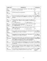
F12

Custom Unit

Enable

Used to enable or disable the custom unit whenever the UNITS key

is  pressed.  This  feature  must  be  disabled  for  commercial

applications.

"0" = Disable custom unit                       "1" = Enable custom unit

0

1

√√√√

F13

Piece Count

Enable

Used to enable or disable the piece count feature. This feature must

be disabled for commercial applications.

"0" = Disable piece count                       "1" = Enable piece count

0

√√√√

1

F14

lb/kg

Conversion

Enable

Used  to  enable  or  disable  the  lb  to  kg  conversion  whenever  the

UNITS key is pressed.

"0" = Disable conversion                       "1" = Enable conversion

0

1

√√√√

F16

Zero

Calibration

Places indicator into the zero calibration routine. Scrolling down with

the 

ZERO

 key one level begins the procedure.

Press 

ZERO

 key

to begin sequence

F17

Span

Calibration

Places indicator into the span calibration routine. Scrolling down with

the 

ZERO

 key one level begins the procedure.

Press 

ZERO

 key

to begin sequence

F18

View Calibra-

tion

Actuates the function that allows you to view both the zero and span

calibration value. The values displayed in this function are valid only

after  Calibration  (F16  &  F17)  has  been  successfully  completed.

Scrolling down with the 

ZERO

 key one level begins the procedure.

Press 

ZERO

 key

to begin sequence

F19

Key-in Zero

Allows you to key-in known zero calibration value in case of memory

loss in the field. Scrolling down with the 

ZERO

 key one level begins

the procedure.

Press 

ZERO

 key

to begin sequence

F20

Key-in Span

Allows you to key-in a known span calibration value in case of mem-

ory  loss  in  the  field.  Scrolling  down  with  the 

ZERO

  key  one  level

begins the procedure.

Press 

ZERO

 key

to begin sequence

F21

Factory Reset

This sub-menu will reset all parameters in the “F”  and  “A”  menu  to

the default settings. USE WITH CAUTION! Password = 38181

Press the 

ZERO

key twice to

execute.

Summary of Contents for PR-3000 Series

Page 1: ...ruary 13 2004 Contents subject to change without notice Salter Brecknell Weighing Products 1000 Armstrong Drive Fairmont MN 56031 Tel 800 637 0529 Tel 507 238 8702 Fax 507 238 8271 E mail sales salter...

Page 2: ...n Item 7 3 3 2 Taring an Item 7 8 Chapter 4 Advanced Features and Operation 9 4 1 Piece Counting 9 Chapter 5 Scale Configuration 10 5 1 Scale Configuration Overview 10 11 5 2 User A Menu 12 5 2 1 Ente...

Page 3: ...internal battery 20 D 4 How long to charge the internal battery 20 LIST OF FIGURES 1 1 PALLET RUNNER 3000 Front Panel 4 3 1 PALLET RUNNER 3000 Display Detail 6 3 2 Function Keys Layout 7 5 1 PALLET RU...

Page 4: ...ed after unpacking the scale A small amount of preparation is necessary before the scale can be used You will find this information in Chapter 2 Please read these instructions carefully and completely...

Page 5: ...Engage the lift mechanism by lowering the hand control It may be necessary to hit the release button before doing so 7 Lift the pallet by cranking the handle in an UP DOWN direction a minimum of 3 com...

Page 6: ...ING 0 Better known as the Center of Zero annunciator this light is active whenever the displayed weight is within 0 25 divisions of true zero N Indicates that the scale is displaying net weight G Indi...

Page 7: ...cale is not at or below Gross zero 2 The scale is not in motion 3 The scale is not in overload see Appendix C for error codes ON Print This key is used to turn the scale ON The Print function is not a...

Page 8: ...he display shows zero weight and turns the NET annunciator on 5 Place the material to be weighed on the container or pallet raise it off the floor and allow the weight indication to stabilize 6 Read t...

Page 9: ...ontainer or pallet you must first tare the container or pallet off by pressing the TARE key 3 If the screen does not show 10 0 press the TARE key once The scale is prompting you to place ten identical...

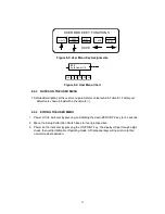
Page 10: ...the switch in the down position as shown at right 4 Power on the indicator by pressing the ON key The indicator shows F 1 to indicate that you are in Setup Menu mode CANNED A D CONVERTER SETUP SWITCH...

Page 11: ...ound in Table 5 1 Factory set defaults are shown in bold with a checkmark 5 2 4 EXITING THE USER MENU 1 Power off the indicator by pressing and holding the down ZERO OFF key for 3 seconds 2 Move the S...

Page 12: ...vel begins the sequence 0 199999 123456 A6 No of line feeds Actuates the function that allows entry of the desired number of line feeds to be printed in the Print Ticket Mode Valid only when A3 is set...

Page 13: ...e indicator must be in standstill to zero the scale 100 1 9 F5 Motion Band Sets the level at which motion is detected by comparing the present display update with the previous one If motion is not det...

Page 14: ...Places indicator into the zero calibration routine Scrolling down with the ZERO key one level begins the procedure Press ZERO key to begin sequence F17 Span Calibration Places indicator into the span...

Page 15: ...15...

Page 16: ...e the zero point value The display will show EndC0 momentarily then revert back up to F16 At this time proceed to the F17 span calibration to complete indicator calibration 6 3 SPAN CALIBRATION F17 1...

Page 17: ...Change the calibration test weight or check the input data Err1 The calibration test weight or the adjusted keyed in weight is smaller than 1 of the full capacity of the scale Change the calibration t...

Page 18: ...Scale Capacity OPERATING TEMPERATURE RANGE 14 F to 104 F 10 C to 40 C POWER SOURCE 2 internal 6V lead acid batteries AC Adapter 12VDC 800 mA Also acts as charger CHARGER See Power Source above Charge...

Page 19: ...eck all load connections Use F16 mode to view internal counts See Appendix C for more information Err 3 All Modes Non volatile memory read error One or more setup parameters have been lost Err 4 All M...

Page 20: ...scale may be used for an additional 15 to 30 minutes without damage to the internal battery If the scale is used for more than 30 minutes after a low battery indication permanent damage may occur to t...

Reviews: