background image

6

.1   Power supply connections

                                  6

   Wiring Diagrams

S122 

User / 

Service Instructions

Wiring Diagrams

Electrostatic sensitive device
Observe all precautions for handling electrostatic 
discharge sensitive devices.

6

.1

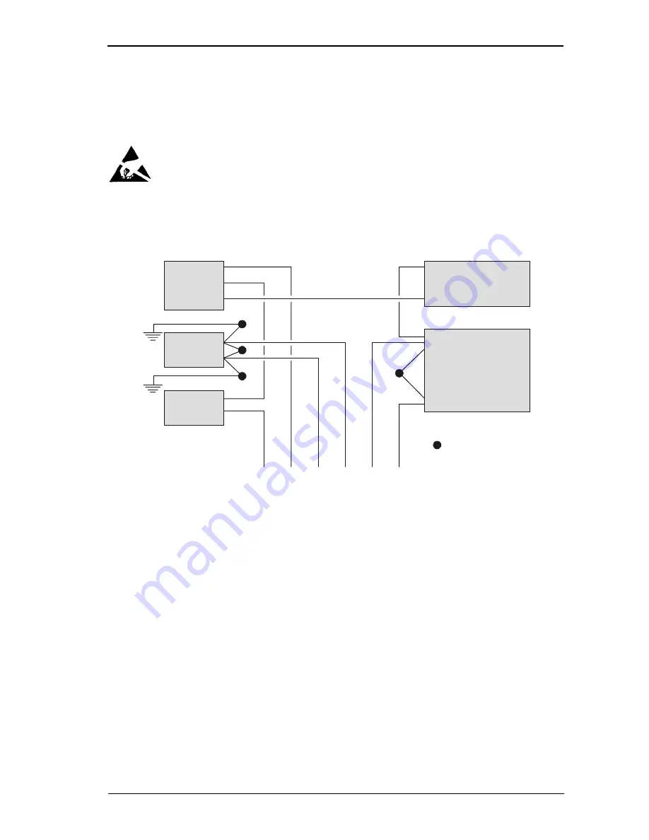
Power supply connections

Note: All connections are soldered.

'D' cell batteries

Internal 

rechargeable

battery

Battery

selector 

switch

AC Power 

in socket

On/off

Switch

Re
d

Black

= 0.1µFCapacitor

Bl

u

e

G

reen

O

ran
ge

Ye
llo

w

Br
o

w

n

To mainboard

Red

Summary of Contents for S122

Page 1: ...76104 180 Issue 0 76104 180 21 07 2004 ENGLISH S122 Light Industrial Scale User Service Instructions...

Page 2: ...IMPORTANT Before using the scale for the first time remove foam packing from under the shroud 1 Lift off weigh plate 2 Remove 4 x foam packaging blocks 3 Replace shroud...

Page 3: ...Brecknell Limited and is supplied without liability for errors or omissions No part may be reproduced or used except as authorized by contract or other written permission The copyright and the forego...

Page 4: ...s 10 2 3 Error messages 12 3 Using the scale 3 1 Zeroing the scale 15 3 2 Data entry keys 15 3 3 Selecting weighing or counting 16 3 4 Using the backlight option 16 3 5 Switching between kgs and lbs 1...

Page 5: ...5 1 1 Service mode keys 35 5 2 Configuration menu 36 5 2 1 F6 exiting configuration mode 37 5 3 F0 weight calibration 38 5 4 F1 specification settings 40 5 4 1 Keyboard check 40 5 5 F2 noise filter s...

Page 6: ...r Service Instructions 6 Contents Wiring Diagrams 6 1 Power supply connections 58 6 2 Main board connections 59 6 3 Load cell connections 60 7 Parts Lists 7 1 Illustrated part lists 61 7 2 Additional...

Page 7: ...pment used out of doors or in wet or damp conditions should be supplied from a correctly fused source and protected by an approved RCD to BS7071 or BS7288 or BS4293 IF IN DOUBT SEEK ADVICE FROM A QUAL...

Page 8: ...h adequate insulation Test probes with claw ends and jumper leads must not have insecure parts that may fail during use 1 4 Safe handling When lifting moving or supporting the scale take its weight in...

Page 9: ...setting for the range of stability from 01 15 3 Depending on the calibration division Standard division under 10000 Capacity and weight must be calibrated High precision division over 10000 to 150000...

Page 10: ...splay to zero Selects units of measure Switches between kgs and lbs Selects counting mode Sample key Displays the number of items in the sample Totalize key Displays the count number and total weight...

Page 11: ...mode Tares off the displayed weight of a container Enables you to enter a tare value when no weight is on the platform To view a tare press followed by the tare key To cancel a tare remove the contai...

Page 12: ...is applied and removed exactly in accordance with instructions E3 Not used E4 The weight on the platform is unsteady E5 There is a problem with the load cell Check the wiring see page 60 If the error...

Page 13: ...to the internal battery When the scale is connected to the AC power supply you will see a red yellow or green charging lamp depending on the condition of the internal battery Using batteries You can...

Page 14: ...connected to the AC power supply and internal battery is being recharged the power supply light will turn red yellow and then green To maintain the rechargeable battery in good condition it should be...

Page 15: ...you are using the scale it means that the weight on the platform is unsteady 3 1 Zeroing the scale Remove any weight from the platform 3 2 Data entry keys Whenever you need to enter values when setti...

Page 16: ...prompted to sample some items 3 4 Using the backlight option Each press of the backlight key shows If set to automatic the backlight comes on automatically when the indicator is being used A backlight...

Page 17: ...larger the sample size the more accurate the counting will be If you see above the piece weight icon it means that the unit weight of each item is too small and this may lead to an inaccurate count C...

Page 18: ...t of the sample the count may be inaccurate count You should select a greater number of samples and add these to the scale 3 7 Counting If you select counting mode and no sample size has been set you...

Page 19: ...tform when finished 3 9 Recalling totals The count number and then the total will each be displayed for a few seconds before returning to the current display For each weight that you want to add The c...

Page 20: ...20 S122 User Service Instructions 3 Using the scale 3 10 Canceling totals 3 10 Canceling totals Press the clear key while the count number or total is displayed CLEAR ENTRY RECALL...

Page 21: ...Setting check weighing limits If you select counting mode and no sample size has been set you will be prompted to sample some items Weighing mode Counting mode Select either weighing or counting mode...

Page 22: ...e 3 11 Checkweighing 3 11 2 To set the lower limit Example 50 items To move along the display To change the displayed value 00005l 4 times 5 times To move along the display 000050 00000l 0 H To enter...

Page 23: ...the scale S122 User Service Instructions 23 4 3 11 3 To set the higher limit Example 1000 items 000 H ENTER To move along the display twice To change the displayed value 001000 To enter the higher lim...

Page 24: ...targets 3 11 5 Limit indicators While using the scale you will see the following indicators to tell you the status of the check weighing The weight number of items is below the lower limit The weight...

Page 25: ...Using tares If you select counting mode and no sample size has been set you will be prompted to sample some items Creating a tare Viewing a tare Canceling a tare...

Page 26: ...Creating a preset tare Example 1lb Reviewing a pre set tare value...

Page 27: ...Canceling a pre set tare...

Page 28: ...weigh plate off the platform and remove the packing material 2 Thread the load cell cable A through the column 3 Fasten the column to the platform using the Allen key B provided 4 Remove the knob C fr...

Page 29: ...t the grounding connector E is attached to the lip of the column If a ferrite bead is used it should hang on wire between connector A and bracket D 6 Fasten the bracket to the column Make sure that th...

Page 30: ...o the bracket until it clicks into place 2 Plug the connector from the platform into the indicator 3 To adjust the angle of the indicator loosen the knob A and move the indicator until it clicks into...

Page 31: ...sensitive devices 1 If required remove the indicator from the column 2 Remove the battery cover 3 Unscrew and remove the two cross head screws 4 Press in the bottom cover at point A to release the cl...

Page 32: ...nd data to an external device such as a printer or computer The default baud rate is 2400 To change the settings see section5 8 The wiring circuit of the RS232 communication board is shown on page 59...

Page 33: ...from the top of the column 6 For legal for trade scales remove the grounded connection 7 Remove the column 8 Remove the two clips holding the cable to the platform 9 Remove the four M8x 20mm socket h...

Page 34: ...ration mode In order to enter configuration mode you must first set the configuration switch to the unlocked position The switch is located under the tamper proof seal above the serial communication s...

Page 35: ...able in service mode Accept the entered values and go to the next section Cancel all values for the current display Go to the next digit or field Increment the value of the current usually flashing di...

Page 36: ...functions press F9 to F0 TARE Page 38 F 0 Function description Function number See page Weight calibration Page 40 F 1 Specification settings Page 44 F 2 Noise filter setting Page 45 F 3 Zero display...

Page 37: ...ons 5 Configuration Mode 5 2 Configuration menu 5 2 1 F6 exiting configuration mode Remember to set the configuration switch back to the locked position Set the configuration switch to the locked posi...

Page 38: ...on F8 is set to hold 0 Please remember The calibration weight must be over 0 weight or any weight less than the full capacity of the machine To change the unit of calibration To change the flashing di...

Page 39: ...calibration Repeat to enter the calibration weight For example to enter 30 lb Place the calibration weight on the platform Press the enter key Remove the calibration weight twice 3 times 3 times ENTER...

Page 40: ...Keyboard check You can perform a keyboard check If the correct code appears when you press a key then you know that the key is functioning correctly see the table below You cannot check the key as it...

Page 41: ...figuration Mode 5 4 F1 specification settings To check a key press the key If there is an error you will see FI ENTER set 17 SEt ENTER 273027 Internal count E63027 E 73 027 Internal count less than 24...

Page 42: ...play digit 6 Not used Examples kg only 100xxx lb only 200xxx kg lb units 120xxx lb kg units 210xxx To change the flashing digit To go to the next digit ENTER U00000 200000 lb primary unit ENTER 200000...

Page 43: ...ht max kg wghtx2 24 60kgx20g 006018 150kgx50g 015045 300kgx100g 003009 130lbx0 05lb 013045 330lbx0 10lb 003309 660lbx0 20lb 066010 Press and to enter the weight settings digit 1 divisions 1 2 or 5 dig...

Page 44: ...etting appropriate to the environment The higher the value the quicker the machine reaches stability but weighing is less accurate If the environment is unstable enter the value 15 If the environment...

Page 45: ...maximum If the load cell gives stable readings set to 0 which is the minimum Ensure the hold function F8 is set to hold 0 Zero display setting 0 default zero display reading within 1 division 2 zero d...

Page 46: ...eckweighing function Ensure the hold function F8 is set to hold 0 To cancel the high low limits and alarm setting Press and to enter the required low limit Low limit 10 divisions 4 times F4 ENTER 0 L...

Page 47: ...hether stable or not and LCD on 2 Whether stable or not beeps and LCD on Check weighing alarm digit 2 0 No beeps 1 OK over low limits and under high limits beeps 2 Under or equal to low limit must be...

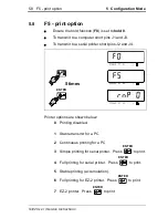
Page 48: ...a serial printer short pins J2 and J4 Printer options are shown below 0 Printing disabled 1 Stable transmit for a PC 2 Continuous printing for a PC 3 Simple printing for serial printer Press to print...

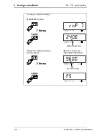
Page 49: ...iguration Mode 5 8 F5 print option To change the printer setting Example EZ 2 printer Display the setting required by the EZ 2 printer Baud rate options are 1200 2400 4800 9600 7 times ENTER Default b...

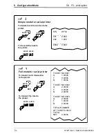
Page 50: ...T NT 2 004lb ST NT 0 000lb ST TR 1 000lb ST NT 0 990lb ST NT 0 990lb ST NT 1 000lb ST NT 1 000lb ST Stable weight NT Gross weight TR Net weight in operation When the weight is stable press the key to...

Page 51: ...he printer S N WT lb _ _ _ _ _ _ _ _ 001 2 000 002 1 000 _ _ _ _ _ _ _ _ 0002 3 000 rnP 4 Full mode for serial printer To transmit each transaction to the printer or ADD ENTER ENTER ENTER To transmit...

Page 52: ...printer S N WT lb _ _ _ _ _ _ _ _ 001 1 000 002 2 000 003 2 000 004 2 000 005 2 000 _ _ _ _ _ _ _ _ 005 9 000 or ADD ENTER ENTER ENTER To transmit the total to the printer rnP 6 Full mode for EZ 2 pr...

Page 53: ...C s UART signal II Format Baud rate Can select 1200 2400 4800 9600 BPS Data bit 8 bits Parity bit None Stop bit 1 bit Code ASCII rnP 7 Stable transmit to EZ 2 printer To transmit each transaction to t...

Page 54: ...s transmission Data 8 bytes 2D HEX minus 2E HEX decimal point Unit 2 bytes kg 6B HEX 67 HEX lb 6C HEX 62 HEX Example 1 0 876kg stable weight and net value Example 2 1 568lb unstable weight and net val...

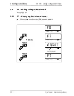
Page 55: ...5 Configuration Mode 5 9 F6 exiting configuration mode 5 9 F6 exiting configuration mode See page 37 5 10 F7 displaying the internal count Ensure the hold function F8 is set to hold 0 7 times F7 ENTE...

Page 56: ...No hold function Hold 1 When the weight is continuously changing the scale automatically holds the maximum value Press any key other than to clear the hold Hold 2 When the weight becomes stable the sc...

Page 57: ...57 S122 User Service Instructions 5 Configuration Mode 5 11 F8 setting the hold function To change the hold setting 8 times F8 ENTER ho1d 0 kg lb ho1d 3 kg lb ENTER F8...

Page 58: ...ice Observe all precautions for handling electrostatic discharge sensitive devices 6 1 Power supply connections Note All connections are soldered D cell batteries Internal rechargeable battery Battery...

Page 59: ...S122 User Service Instructions 6 2 Wiring Diagrams 6 2 Main board connections 6 2 Main board connections...

Page 60: ...6 3 Load cell connections 6 3 Wiring Diagrams S122 User Service Instructions 6 3 Load cell connections...

Page 61: ...7 1 Illustrated part lists 7 1 Parts Lists S122 User Service Instructions 7 Parts Lists 7 1 Illustrated part lists User service Instructions 76103 986...

Page 62: ...ER L120 0002 Ground spring SER L120 0003 On Off switch 1111001111 Battery selector switch 1111001221 Load cell connector male 5 way 1240001051 Load cell connector male 6 way 1240001061 Load cell conne...

Page 63: ...cts described herein may vary from time to time and may be altered without notice USA Salter Brecknell Weighing Products USA 1000 Armstrong Drive Fairmont MN 56031 Toll Free 800 637 0529 Phone 507 238...

Reviews: