All contents current at time of publication.
SALTO Systems S.L. reserves the right to change availability of any
item in this catalog, its design, construction, and/or materials.
225142-ED. - 11/01/2019
©
2019 SALTO Systems S.L.
Lock installation
Lock-Installation
Instalación de la cerradura
Installation de la serrure
D
Eng
E
F
Eng
D
8m
m
m
in
.
1mm
25m
m m
in.
E
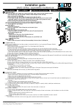
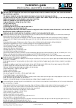
PREPARING THE DOOR
NOTE: if the strike already exists in the door frame, position latch using the strike as reference.(See strike position on template)
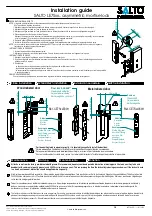
1. Draw a horizontal line on both sides and edge of the door at the desired height of handle above floor.
2. Draw a vertical centre line on door edge.
3. Draw a vertical line on each side of the door at the proper backset to align the template.
4. Position templates on edge and sides of door. Mark only top and bottom holes of mortise cavity (A) and lock front (B)
on door edge, and holes in the lateral face of the door for handles (C) and cylinder (D) (only needed in inside face).
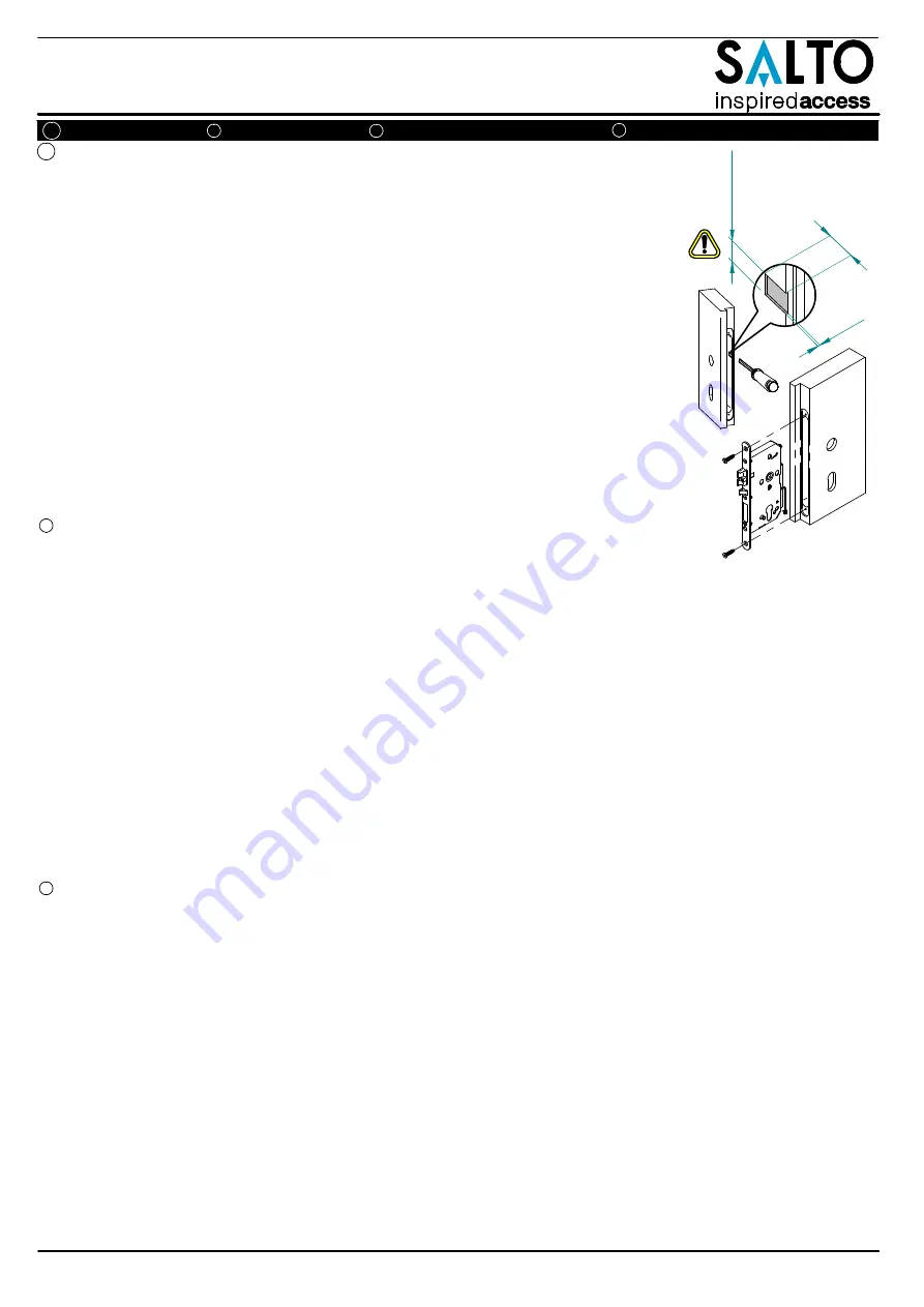
5. Remove the template. Make door preparation of the lockcase according to (A).
6. Insert the lockcase.Draw the outline using the face plate as template for door preparation.
NOTE: Holes for fixation of SALTO electronic escutcheon are not included in this template. Please
use the template in the escutcheon box.
INSTALLING THE LOCK
1. Insert the lock into the cavity.
2. Mark & drill faceplate holes. Fasten with faceplate screws to hold lock in place.
INSTALLING THE STRIKE
1. Refer to latch to determine strike location on jamb.
2. Using strike as template, mark and chisel recess. Drill screw holes. Place dust box and strike
and fasten with the supplied screws.
3. Please check if:
- Deadbolt and latch fit the cavities of the strike without touching it.
- Gap between door and jamb is between 2-4 mm.
- Strike flap should protrude at least 2mm, if it does not, please ask your distributor for the
availability of special strikes.
CABLE CONNECTION
For models with detectors, connect according to the corresponding electronic escutcheon installation guide.
VORBEREITUNG DER TÜR
HINWEIS: wenn das Schließblech bereits in der Zarge vorhanden ist, positionieren Sie die Falle so, dass die vorhandene Öffnung passt. (Beispiel in
der Schablone für das Schließblech).
1. Zeichen Sie eine horizontale Linie auf beiden Seiten der Tür, auf Höhe der gewünschten Drückerposition.
2. Zeichnen Sie eine vertikale Zentrierungslinie.
3. Zeichnen Sie eine vertikale Linie auf beiden Seiten der Tür beim entsprechenden Dornmaß, damit Sie die Schablone korrekt ausrichten können.
4. Positionieren Sie die Vorlage auf der Tür und den Seiten..Markieren Sie nur das obere und untere Lock für die Schlosstasche (A) und Schlossbefestigung (B).
Zusätzlich auf den Seiten der Tür die Bohrung für den Drücker (C) und Zylinder (D) (Wird nur auf der Innenseite benötigt).
Entfernen Sie die Schablone: Legen Sie das Stulp mit der Falle gegen das Türblatt, ausgerichtet an den Befestigungsbohrungen (B). Anschließend Zeichen Sie die Umrisse des Stulp an.
5. Entfernen Sie die Schablone. Vorbereitungen für die Schloss tasche nach (A) ausführen.
6. Stecken Sie das Einsteckschloss in die Schlosstasche und zwichen Sie das Stulpbetch an.
HINWEIS: Die notwendigen Bohrungen für einen SALTO elektronischen Türbeschlag sind nicht in dieser Vorlage enthalten. Bitte verwenden Sie dazu die Schablone, welche dem Beschlag beiliegt.
INSTALLATION DES SCHLOSSES
1. Stecken Sie das Schloss in die Schlosstasche.
2. Markieren und erstellen Sie die Befestigungsbohrungen, anschließend schrauben Sie das Schloss fest.
INSTALLATION SCHLIESSBLECH
1. Benutzen Sie die Falle des Schlosses als Referenz um die korrekte Position des Schließblechs zu ermitteln.
2. Benutzen Sie das Schließblech als Vorlage und markieren Sie die Umrisse, sowie Position der Ausschnitte und Befestigungslöcher.
3. Erstellen Sie die Ausnehmungen und Befestigungsbohrungen. Positionieren Sie den Staubschutz in den Ausnehmungen und befestigen das Schließblech mit den beiliegenden Schrauben.
4. Bitte prüfen Sie:
- Falle und Riegel passen in das Schließblech ohne zu klemmen.
- Das Spaltmaß zwischen Zarge und Türblatt sollte 2 – 4mm betragen.
- Das Schließblech sollte max. 2mm vorstehen, wenn dies nicht passt fragen sie bitte bei Ihrem Türlieferanten nach einem speziellen Schließblech.
KABELVERBINDUNG
Bei Modellen mit kontaktabfrage, bitte zum Anschulun des elektronischen Beschlags beachten.
PREPARACIÓN DE LA PUERTA
NOTA: Si existe un cerradero ya instalado en el marco, use esta referencia para fijar su posición (Mire la posición del cerradero en la plantilla).
1. Dibuje una línea horizontal en ambos lados y borde de la puerta, a la altura deseada de la manilla desde el suelo.
2. Dibuje una línea vertical en el eje deseado del canto de la puerta.
3. Dibuje una línea vertical a cada lado de la puerta para fijar la entrada y poder alinear la plantilla.
4. Coloque la plantilla en los lados y en el borde de la puerta. Marque solamente los agujeros superior e inferior de la caja (A) y frente (B) de la cerradura en el borde de la puerta, y los
laterales para manilla (C) y cilindro (D) (solo necesario en la
cara interior).
5. Quite la plantilla. Realice el mecanizado para cerraduras según marca (A).
6. Introduzca la cerradura. Marque el contorno del frente para realizar el cajeado del mismo.
NOTA: Los agujeros de fijación del escudo electrónico SALTO no están incluidos en esta plantilla. Use la plantilla incluida en el embalaje del escudo electrónico.
INSTALACIÓN DE LA CERRADURA
1. Inserte la cerradura en la cavidad.
2. Marque y perfore los agujeros del frente. Sujete con los tornillos el frente de la cerradura en su alojamiento.
INSTALACIÓN DEL CERRADERO
1. Tome la referencia el eje del picaporte para determinar la posición del cerradero.
2. Usando el cerradero como plantilla, marcar su perfil, cajear con el formón y perfore los agujeros. Coloque la caja-cerradero y sujete el cerradero con los tornillos suministrados.
3. Comprobar:
- El picaporte y la palanca entran en los huecos del cerradero sin rozar.
- Holgura entre puerta y marco, entre 2 mm y 4mm.
- La solapa del cerradero debe sobresalir mínimo 2 mm, de lo contrario, consulte con su distribuidor, la disponibilidad de cerraderos especiales.
CONEXIÓN CABLE
En caso de modelos con detectores, realizar conexión según guía de instalación del escudo electrónico correspondiente.
Installation guide
SALTO LE7Sxx.. asymmetric mortise lock
2/4


