Tel: 886. 909 602 109 Email: sales@salukitec.com
www.salukitec.com
81
filter, click this button again and it will reset to the start status
. This means you have closed the sync
filter successfully.
8. Output Configuration
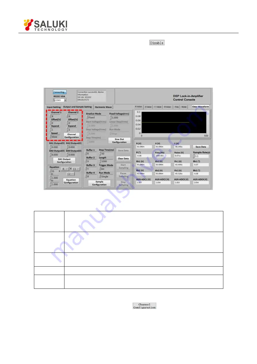
The output configuration is in the red box in the Fig.67. The details of configuration are shown in Table 9.
Fig.67 The Configuration Area of Output Channel
Table 9. Output Channels Configuration Options
Channel 1
Choose CH1 to output the required values. The value types contain the
X/Y/R/θ value of signal and signal harmonic, the noise value and the
E1/E2/E3/E4 value.
Channel 2
Choose CH2 to output the required values. The value types contain the
X/Y/R/θ value of signal and signal harmonic, the noise value and the
E1/E2/E3/E4 value.
Offset (%)
The range is -100% to +100%, the minimal step is 0.01%, 0.00% in default. It
can only set the R/X/Y value.
Expand
The range is 1 to 256, 1 in default.
Speed
Choose “Fast” /” Slow”. When choosing “Fast”, the CH1 and CH2 can only
output the R/X/Y value.
Note that:
After setting the output configuration, click the button
to finish the configuration; all settings can
be changed at the same time and you just need to click this button once.


