Tel: 886. 909 602 109 Email: sales@salukitec.com
www.salukitec.com
21
2 Interfaces
2.1 Front Panel
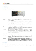
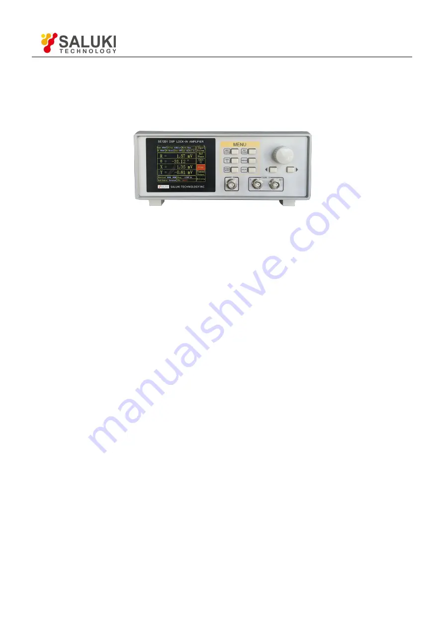
The front panel of SE1201 is shown in Fig.8.
Fig.9 Front Panel of SE1201
Display
The SE1201 uses 3.5-inch TFT-LCD for display and interactive control. Display
resolution is 320*240.
8 levels of background brightness are available, which is set in [Utility] in [SYSTEM].
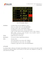
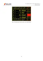
When in the [Display] menu, the left of the screen displays the measurement results of the
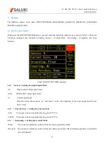
input signal. Otherwise, the left of the screen displays the corresponding submenu
currently.
Spin Knob
Press the spin knob to highlight or exit the current parameter.
If a parameter is highlighted now, spin the knob to change its value. If no parameter is
highlighted, spin the knob to select different submenu.
Keyboard
There are two groups of keyboards: MENU and two buttons under the spin knob
which are called the left button and the right button. The six buttons at MENU
correspond to six different menus. The left and the right buttons are used to adjust the
highlighted parameter at current menu.
BNC Connectors
REF IN
The reference input can be a sine wave or a TTL pulse. When input is a sine wave, the input
impedance is 1M
Ω
AC coupled. For low frequencies (<1Hz), it is necessary to use a TTL
reference signal.
SIGNAL IN
There are two signal input modes, single-ended A and differential, A-B. The input A can be
current signal. When measuring voltage, the input impedance of A and B are both 10
MΩ//25pF. When measuring current, the input is connected to the ground via a 1kΩ resistor.
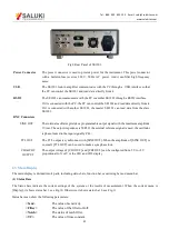
2.2 Rear Panel
The rear panel of SE1201 is shown in Fig.9. It includes a cooling fan, a power connector, a power switch, an USB
interface, a RS232 interface and four BNC connectors. The four BNC connectors are named [SINE OUT], [CH1 OUT],
[CH2 OUT] and [TTL OUT] respectively.


