Tel: 886. 909 602 109 Email: sales@salukitec.com
www.salukitec.com
22
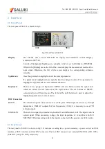
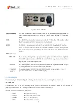
Fig.9 Rear Panel of SE1201
Power Connector
The power connector is used to provide power for the instrument. This power connector
with a build-in fuse receives 220 V, 50 Hz AC power. And it can filter high frequency
noise.
USB
The SE1201 lock-in amplifier communicates with the PC through a USB interface so that
the PC can control the SE1201 and read data directly from it.
RS232
The SE1201 can communicate with the PC or another SE1201 through a RS232 interface.
If it is connected with the PC, the PC can control the SE1201 and read data directly from it.
If it is connected with another SE1201, the master SE1201 can read data from the slave
SE1201.
BNC Connectors
SINE OUT
The internal oscillator provides a programmable output signal with the maximum amplitude
1Vrms. The output impedance is 50
Ω
. If the external reference signal is used, the oscillator
is phase-locked to the input signal by PLL.
TTL OUT
The TTL output is synchronous with [SINE OUT]. When the amplitude of [SINE OUT] is
so small, [TTL OUT] can be used to make a sync phase lock.
CH1&CH2
OUTPUT
The output voltage of [CH1 OUT] and [CH2 OUT] can be configured from -5V to +5V
proportional to X or Y or the CH1 and CH2 display.
2.3 Main Display
The main display is divided into 4 parts, including status bars, function bar, monitoring bar and menu bar.
(1) Status Bars
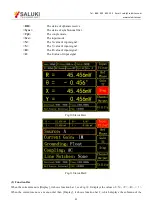
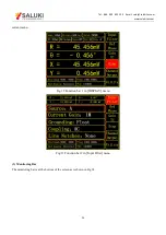
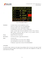
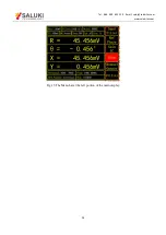
The Status bars indicate the current settings of the system or the results of measurement. When the current menu is
[Display], it shows status bar 1, see Fig.10. Otherwise, it shows status bar 2, see Fig.11.
Status bars can show the following parameters:
<Sens>
The value of sensitivity
<Filter>
The value of the filter roll-off.
<Notch>
The status of notch filter.
<TC>
The value of time constant.


