Tel: 886. 909 602 109 Email: sales@salukitec.com
www.salukitec.com
27
3 Menus
The MENUs consists of six parts: [INPUT/FILTERS], [REF/PHASE], [GAIN/TC], [DISPLAY], [CHANNEL
OUTPUT] and [UTLITY].
3.1 [INPUT/FILTERS]
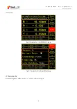
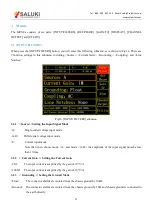
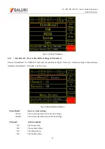
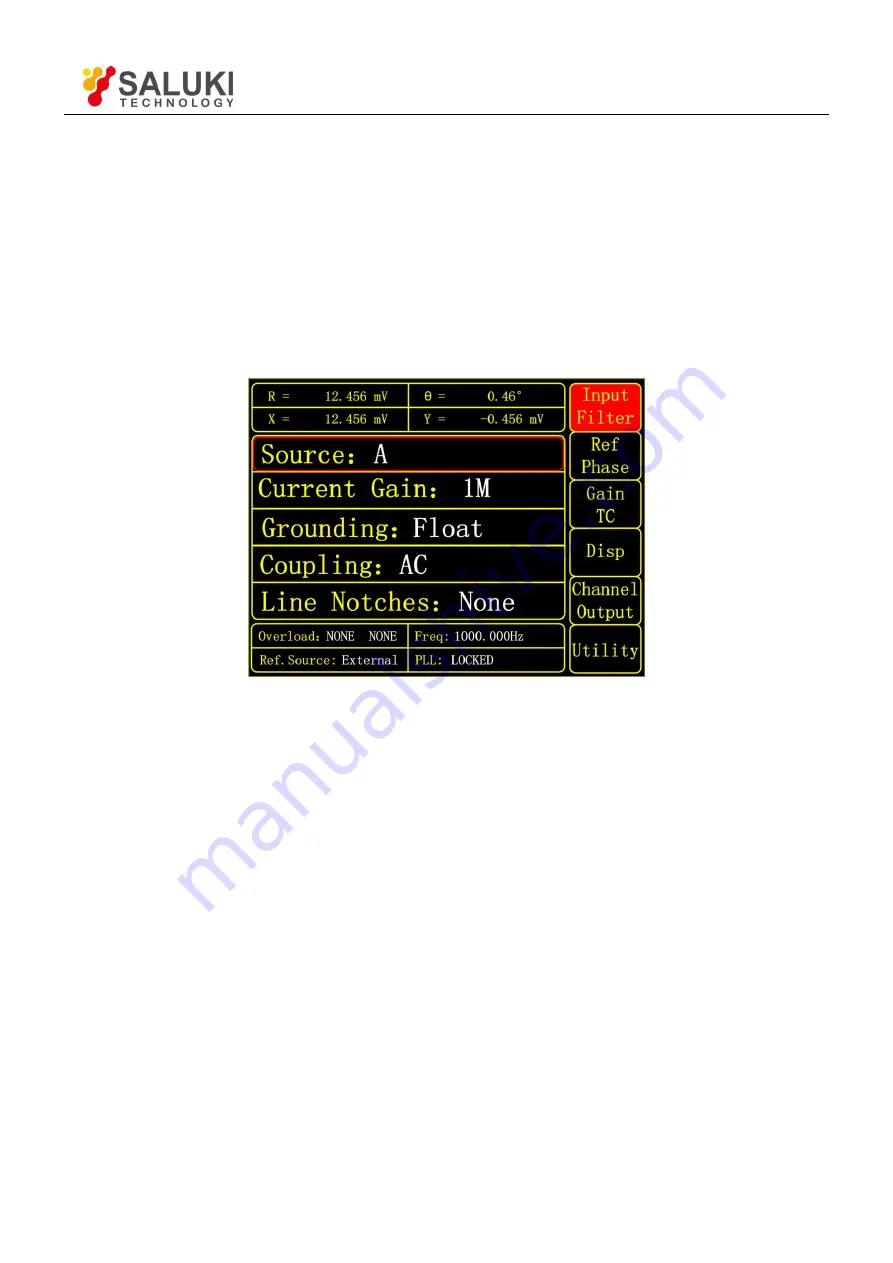
When press the [INPUT/FILTERS] button, you will enter this following submenu, as is shown in Fig.16. There are
5 function settings in this submenu, including <Source>, <Current Gain>, <Grounding>, <Coupling> and <Line
Notches>.
Fig16. [INPUT/ FILTERS] submenu
3.1.1 <Source>: Setting the Input Signal Mode
<A>
Single-ended voltage input mode.
<A-B>
Differential voltage input mode.
<I>
Current input mode.
Note that when choose mode <A> and mode <A-B>, the amplitude of the input signal must be less
than 1Vrms.
3.1.2 < Current Gain >: Setting the Current Gain
<1M>
The input current is amplified by the gain of 10
6
V/A.
<100M> The input current is amplified by the gain of 10
8
V/A.
3.1.3 < Grounding >: Setting the Ground Mode
<Float>
The connector shields are isolated from the chassis ground by 10kΩ.
<Ground> The connector shields are isolated from the chassis ground by 10Ω and chassis ground is connected to
the earth directly.


