Tel: 886. 909 602 109 Email: sales@salukitec.com
www.salukitec.com
33
V
5
180
rce)
Signal(sou
=
Output
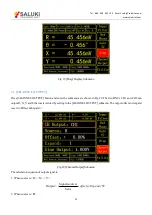
3.6.1 < CH Output >: Setting the Output Channel
<CH1>
Setting CH1 as the output channel
<CH2>
Setting CH2 as the output channel
3.6.2 < Source >: Setting Output Source
<X>:
<Y>:
<R>:
<θ>:
the corresponding analog level of the channel output X
the corresponding analog level of the channel output Y
the corresponding analog level of the channel output R
the corresponding analog level of the channel output θ
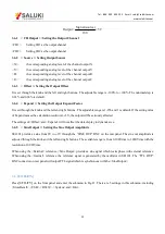
3.6.3 < Offset >: Setting the Output Offset
It is set through the knob and the left and right buttons. The adjustable range is -100% to +100%. The minimal step is
0.01% and 0.00% is default.
3.6.4 < Expand >: Setting the Output Expand Factor
It is set through the knob and the left and right buttons. The adjustable range is 1-256 and 1 is default. If the setting value
of Expand causes the calculation result over ±5V, the output will be seriously affected.
The settings of <Offset> and <Expand> will not affect the data display in dynamic area.
3.6.5 < Sine Output >: Setting the Sine Output Amplitude
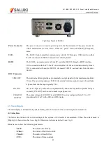
SE1201 provides a sine from 0V to ±1V through the “SINE OUT” BNC on the rear panel. The sine out amplitude is
adjusted through the knob and the left and right buttons. The available range is from 0.100Vrms to 1.000Vrms with the
resolution of 0.001Vrms.
When using the <External> reference, <Sine Output> provides a sine signal which locks phase with external reference.
When using the <Internal> reference, the reference signal is generated by the oscillator in SE1201. The “TTL OUT”
BNC connector on rear panel will output TTL signal which is synchronous with the <Sine Output>.
3.6
[UTILITY]
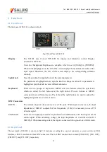
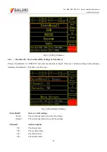
Press [UTILITY] on the front panel and enter the submenu in Fig.21. There are 5 settings in this submenu, including
<StoreRecall>, <USB>, <RS232>, <System> and <Info>.

