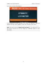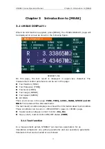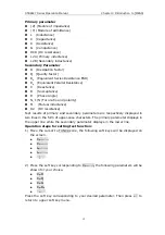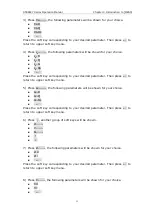
STB8827
Series Operation Manual Chapter 2 Introduction
Chapter 2 Introduction
In this chapter, the basic operation features of
STB8827
series are described
. Please read the content carefully before using
STB8827
series instruments,
thus you can learn the operation of
STB8827
.
2.1 Introduction to front panel
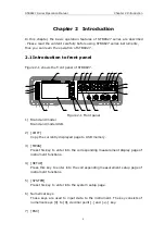
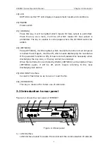
Figure 2-1 shows the front panel of
STB8827
.
POWER
CATⅠ
!
±42VDC Max
MEAS
SETUP
SYSTEM
L
POT
H
POT
UNKNOWN
COPY
PQRS
9
8
TUV
WXYZ
6
5
GHI
JKL
MNO
7
4
3
2
1
ABC
DEF
L
CUR
ENTER
ESC
+/-
0
RESET
KEYLOCK
DC BIAS
DC
SOURCE
PASS
FAIL
TRIGGER
H
CUR
LOG
STB8827C Precision LCR Meter
20Hz-1MHz
1
20
19
6
9
15
14
18
2
17
16
7
10
23
22
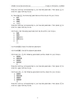
21
8
11
12
13
3
4
5
Figure 2-1 Front panel
1) Brand and model
Brand and model USB.
2) [COPY]
Copy the currently displayed page to USB memory.
3) [MEAS]
Press this key to enter into the corresponding measurement display page of
instrument functions.
4) [SETUP]
Press this key to enter into the corresponding measurement setup page of
instrument functions.
5) [SYSTEM]
Press this key to enter into the system setup page.
6) Numerical keys
These keys are used to input data to the instrument. The key consists of
numerical keys [0] to [9], decimal point [.] and [+/-] key.
7) [ESC]
4


