STB8827
Series Operation Manual Chapter 7 Command Reference
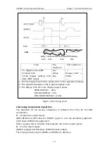
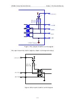
Control output signal
/INDEX (analog test finished signal),
114
/EOM (test ended and the compared
data effective), /ALARM (the circuit interruption)
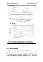
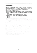
Control input signal
/EXT.TRIG (external trigger signal), /Keylock (the key lock).
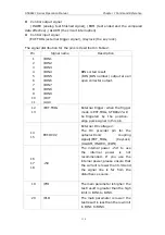
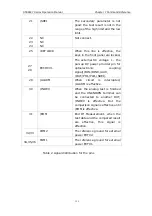
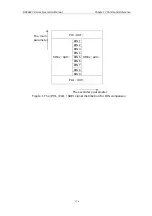
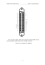
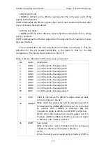
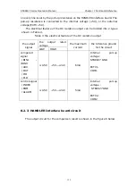
The signal distribution for the pins is described in Table 2:
Pin Signal
name
Description
/BIN1
/BIN2
/BIN3
/BIN4
/BIN5
/BIN6
/BIN7
/BIN8
/BIN9
/OUT
1
2
3
4
5
6
7
8
9
10
11
/AUX
BIN sorted result
/BIN (BIN number) output are all
open collector output.
12
13
/EXT.TRIG
External trigger: when the trigger
mode is EXT.TRIG,
STB8827
will
be triggered by the positive-
edge pulse signal in this pin.
14
15
External DC voltage 2:
The DC provider pin for the
optoelectronic coupling
signal(/EXT_TRIG, /KeyLock,
EXT.DCV2
/ALARM, /INDEX, /EOM)
16
17
18
The internal power +5V: to use
the internal power is not
recommended. If you use the
internal power, please ensure that
the current is lower than 0.3A and
the signal line is far from the
+5V
disturbance source.
19
/PHI
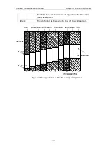
The main parameter is higher: the
test result is greater than the high
limit in BIN1 to BIN9.
20
/PLO
The main parameter is lower: the
test result is less than the low limit
in BIN1 to BIN9.

