ENGLISH
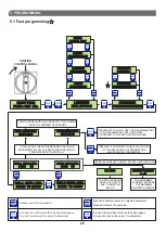
6. GENERAL FUNCTIONING OF THE CONTROL PANEL
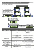
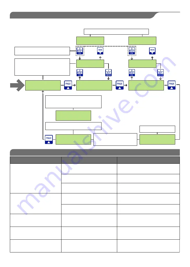
6.3 Application 4-20mA bar
400 V 13.2 A 13.2 A
1.5 bar
AUTOMATIC MOT. 1
13.2 A 0h
STOP MOTOR 1
0.0 A 0h
6.1
SYSTEM PRESSURE
1.5 bar
AUTOMATIC MOT.2
13.2 A 0h
STOP MOTOR 2
0.0 A 0h
MANUAL MOTOR 1
13.2 A 0h
MANUAL MOTOR 2
13.2 A 0h
NO WATER
WAITING
FILLING
IT IS USED TO START THE MOTORS MANUALLY
ONLY IN STABLE MANUAL
BUTTON MODE
THE FOLLOWING SCREENS DISPLAY:
- MEASURED VOLTAGE
- ABSORBED CURRENT OF THE MOTORS
- OPERATING HOURS OF THE MOTORS
- SYSTEM PRESSURE
IT DISPLAYS THE SYSTEM
PRESSURE DETECTED
THIS SCREEN IS DISPLAYED WHEN
THE MINIMUM PROBE IS UNCOVERED
THIS SCREEN IS DISPLAYED WHEN THE
MINIMUM PROBE IS COVERED AND
THE MAXIMUM PROBE IS UNCOVERED
AFTER THE LACK OF WATER
IF THE MOTHERBOARD DETECTS
A DRY RUNNING CONDITION IT
WILL BE POSSIBLE TO DISPLAY
A FIFTH SCREEN
27
7.
TROUBLESHOOTING AND PROPOSED SOLUTIONS
Pressure BOOSTER application:
PRESSURE SWITCHES OFF
status with low pressure system
Possible failure of the pressure switches
FREQUENT PROBLEMS
CAUSES
OPERATION
Feed the control panel respecting
the input voltage
Set the switch on 1
Connect the flat cable from the motherboard
to the display
Switch set on 0
Display off
N
o supply
The flat cable inside the control panel
is not connected
MAXIMUM CURRENT
motor 1 and 2 alarm
Maximum current set on the setup less
than that absorbed by the motor
Motor blocked or damaged
Set manually the maximum current the 25%
more than the nominal value
Disconnect the motor and be sure
it is working properly
Application 4-20mA bar:
Pressure value in bar displayed
in the wrong display
Clean carefully the pressure transducer
or
replace if necessary
Possible obstruction or failure of the
4-20mA pressure transducer
Ceck the functionality of the pressure switches
and of the cable and replace if necessary
NO WATER
with presence of water in the well
Possible probe failure or sensitivity
set too low
Ceck the probes sensitivity and
replace them if necessary;
set the probes sensitivity


