
ENGLISH
Make sure power supply is protected up to standard depending on application. The power of the
motor has to be within the control panel's limits of use.
Before acting upon anything inside, disconnect power supply. Regulation procedures must be
carried out by qualified personnel. In case protections intervene verify the cause of the problem
before resetting.
The manufacturer is released from all responsibilities for accidents to things or people, which
derive from misuse of the devices by unauthorized personnel or from lack of maintenance
and repair.
Install the control panel in an environment appropriate to its IP65 degree of protection. To fix the
enclosure, use the brackets for the boxes 03-04 and the special predispositions for the remaining
boxes. In order to fix the box, use the appropriate holes which are present or suggested on the
bottom. Pay particular attention to not touching or damaging any components while fixing the box.
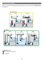
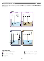
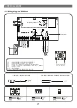
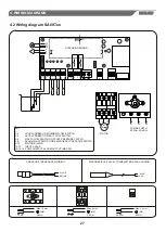
When connecting electric cables, follow the wiring diagrams.
When fixing the cables in the terminal board use tools of correct size to avoid damaging the metal
feed clamps and their sockets.
It is the installer' s duty to verify the device after the installation although it has already
undergone regular testing by the manufacturer.
Eliminate whatever metal and/or plastic impurity which could happen to fall inside the box (screws,
washers, dust…).
If necessary substitute the various components only with those having the same characteristics and
components as the originals.
1.
GENERAL INSTRUCTIONS FOR INSTALLING
2.
WARNINGS
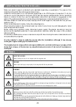
ELECTRIC SHOCKS
Risk of electric shocks if not complied with the requirements.
DANGER
Risk of personal injury and property if not complied with the requirements.
WARNING
Before installing and using the product read this book in all its parts. Installation and maintenance must be
performed by qualified personnel in accordance with current regulations.
The manufacturer will not be held responsible for any damage caused by improper or prohibited use of this
control panel and is not responsible for any damages caused by an incorrect installation or maintenance of the
plant. The use of non-original spare parts, tempering or improper use, make the product warranty null.
Be sure that the power of the motor is within the control panel range.Install the control panel in an environment
appropriate to its IP
65 degree of protection.
WARNING
To operate inside the control panel use tools of correct size to avoid damaging the sockets.
In order to fix the box use the appropriate holes present on the bottom, don't damage internal components and
eliminate any working debris inside the box.
Do not attempt operations when the control panel is open.The control panel must be connected to an efficient
earthing system.
DANGER
Before any intervention ensure that the control panel is disconnected from the electricity supply.
In the case of protections eliminate the cause of the malfunction before the restoration.
3
23
Summary of Contents for MULTIPLUS 1 SA684 Series
Page 24: ......


