background image

4

This product complies with the essential requirements and other relevant provisions of Directives 2014/53/EU and 2011/65/EU. The full text of the EU 
Declaration of Conformity is available at the following internet address: www.saluslegal.com.

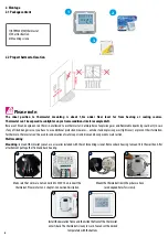
• Before starting installation work and before using the product, read the entire manual.
• The information contained in the instructions is essential for proper functioning.
• To avoid accidents resulting in personal injury and material damage, please follow all safety precautions, specified in this manual.
• The device should not be used by people with limited mental, sensory or mental abilities, without experience, of insufficient knowledge as well as 
children.
• Do not use an unassembled device (eg without a cover).
• The device may only be opened by a qualified person.
• Keep electrical devices out of the reach of children and ensure that they do not play with it. Children should not be left unattended. If necessary, 
disconnect the control system for the entire room.
• Do not leave the packaging, cabinet, or any loose parts of the device unattended, as they pose a risk to children.

WARNING!

• Installation must be carried out by a qualified person with appropriate electrical qualifications in accordance with standards and regulations in force in 
the given country and in the EU.
• Never try to connect the device other than as described in the manual.
• Before assembly, repair or maintenance as well as during any connection works it is absolutely necessary disconnect the mains supply and make sure 
that the terminals and electric wires are not live.
• The device may not be exposed to extreme temperatures, strong vibrations or subjected to mechanical shock.
• The device should not be used in unfavorable environmental conditions or in rooms where there is a concentration of flammable gases, fumes or dust.

WARNING!

• There may be additional protection requirements for the entire installation that the installer is responsible for maintaining.

1. Introduction

1.1 Product Compliance

1.2 Safety Informations

Care for the natural environment is of paramount importance to us. The awareness that we manufacture electronic devices obliges us 
to dispose of used electronic components and devices safely. Therefore the company has received a registration number issued by the 
Chief Inspector for Environmental Protection. The crossed out symbol the trash can on the product means that the product must not be 
disposed of with ordinary waste containers. Sorting waste for recycling helps to protect the environment. It is the user’s responsibility 
to surrender used equipment to a designated collection point for recycling waste from electrical and electronic equipment.

Summary of Contents for BTRP230V

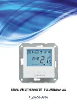
Page 1: ...BTRP230V 50 THERMOSTAT FULL USER MANUAL...

Page 2: ......

Page 3: ...heating source control 14 III B work with RM 16A relay module connection to a solid fuel boiler controller 14 III C work with RM 16A relay module connecting an electrical device with a higher power 1...

Page 4: ...tions in accordance with standards and regulations in force in the given country and in the EU Never try to connect the device other than as described in the manual Before assembly repair or maintenan...

Page 5: ...should reach while it is on It will allow you to select different temperatures in your home at different times of the day and days of the week to meet your particular needs Turning a programmable roo...

Page 6: ...d explosion risk there is not allowed to use thermostat in atmosphere of explosive gases and flammable liquids eg coal dust In case if any of listed dangers occur you have to use additional protection...

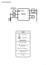
Page 7: ...er between heating and cooling input 230V AC S1 N additional temperature sensor eg FS300 2 3 Connection description Wej cie NSB w regulatorze SLAVE BTRP BTRP 230 Wyj cie NSB L N S1 N CO L AC 230V N T3...

Page 8: ...0 thermostat works as a MASTER group controller it means it takes control of SLAVE thermostats e g BTR230V 20 MASTER thermostatcontrolsSLAVEthermostatonlywhenSLAVEthermostatisinAUTOmode Comfort SUN an...

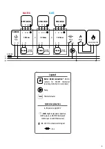
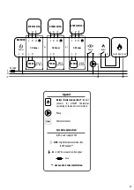
Page 9: ...Zones 3 4 N N N N N N L max 6 per zone max 6 per zone max 6 per zone BTRP230V 50 BTR230V 20 BTR230V 20 L N power supply 230V NSB Night temperature reduction 230V output in MASTER thermostat 230V input...

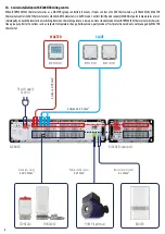
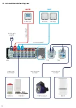
Page 10: ...tre THB23030 T30NC230 Power Supply 230V AC Actuators wires 2 x 0 75mm2 Pump control wires 2 x 1mm2 Boiler control wires 2 x 1mm2 KL06 PL07 PL06 PUMP optional BOILER 4 wires x 0 75 mm2 4 wires x 0 75 m...

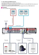
Page 11: ...Power L N L N T30NC max 6 na stref RT10 RT20 Np Np L N 1 6 Strefy PL06 L N L N T30NC max 6 na stref RT520 COM NO lub NC NO POD CZENIE KOT A L AC 230V L N N 1 6 Strefy KL06 M Power L N L N T30NC max 6...

Page 12: ...hermostat no effect on other thermostats like BTR230V 20 schedules can be set individually on each BTRP230V 50 thermostats if system is equipped with more than one BTRP230V 50 thermostat PLEASE NOTE T...

Page 13: ...8 Zones 3 4 N N N N N N L max 6 per zone max 6 per zone max 6 per zone BTRP230V 50 BTRP230V 50 BTRP230V 50 L N power supply 230V NSB Night temperature reduction 230V output SL 230V AC actuator contro...

Page 14: ...O COM COM NC SL N L L N 1 8 Strefy KL08NSB Power L N L N SL Connection of a 230V AC voltage thermostat to a boiler or other device with an ON OFF contact BTRP230V 50 BOILER CONNECTION input PLEASE NOT...

Page 15: ...8 Strefy KL08NSB Power L N L N SL MA 16 5 input BTRP230V 50 III C work with RM 16A relay module connecting an electrical device with a higher power than the thermostat relay allows PLEASE NOTE The ma...

Page 16: ...ling mode ON 16 Heating mode ON 16 15 11 12 13 14 7 8 9 10 1 2 3 4 5 6 PLEASE NOTE The LCD screen can be activated by using any button OR 1 Increase or decrease setpoint temperature 2 Increase or decr...

Page 17: ...ons Confirm by button After all the main screen will be displayed Set time format or buttons Confirm by button Set time hours and minutes using or buttons Confirm by button then thermostat will displa...

Page 18: ...lly set when we are indoors The highest maintained temperature in heating mode or the lowest if thermostat works in the cooling system Acting alone works as a manual mode Temperature range from 5 C to...

Page 19: ...e are 4 possible schedule variants Use and buttons to select schedule variant and confirm by button Separate schedule for WORKING DAYS Separate schedule for WEEKENDS One schedule for WHOLEWEEK Seven s...

Page 20: ...is skipped There are 6 programs time periods in the schedule Hold button for 3 seconds to save and exit schedule editing To run the schedule activate thermostat s automatic mode use and buttons to mo...

Page 21: ...4 5 6 2 days Saturday to Sunday Program Program Time Heat set point Cool set point 1 7 00 2 23 00 3 4 5 6 Program Profile 3 5 days Monday to Friday Program Program Time Heat set point Cool set point 1...

Page 22: ...by button Set minutes using and buttons Confirm by button Set day using and buttons Confirm by button 3 DATE settings will automatically appear after clock setup Hold button for 3 seconds to enter th...

Page 23: ...C in 0 5 C steps To calibrate thermostat s temperature sensor please follow steps below 1 4 7 6 Set temperature calibration value using and buttons To increase decrease value use and buttons Go to th...

Page 24: ...hen thermostat automatically switches to cooling mode Set thermostat for heating using and buttons Confirm by button 2 1 1 2 AUTOMATICALLY By external ON OFF switch MANUALLY 3 Wej cie NSB w regulatorz...

Page 25: ...s an advanced algorithm designed to precisely maintain room temperature 0 1 SPAN 0 25 C 0 5 F 2 SPAN 0 5 C 1 0 F d02 Room temp offset 3 0 C to 3 0 C Offset room temperature measuring is a function whi...

Page 26: ...minimum setpoint for heating and cooling modes Default temperature setting range 5 C 40 C 5 C d14 Floor sensor protection limit heating high limit HL 11 C 45 C Turn off relay output when floor sensin...

Page 27: ...factory default settings please follow steps below 1 2 3 4 7 5 6 Wait few moments to finish factory reset procedure thermostat will display the software version after all screen with time and date sel...

Page 28: ...tion PWM Yes Clock Timer Yes programmable Heating and Cooling Yes automatic modes changeover through CO terminal Parameter adjustment Yes in Installer Mode Dimensions 71mm x 71mm x 46mm TheBTRP230V 50...

Page 29: ...illbefreefromanydefectinmaterialsorworkmanship andshallperforminaccordancewithitsspecification foraperiodoffiveyearsfromthedateofinstallation SALUSControlssoleliabilityforbreachofthiswarrantywillbe at...

Page 30: ...OLS Sp z o o Sp k Rolna 4 43 262 Kobielice Poland www salus controls com SALUS Controls is a member of the Computime Group Maintaining a policy of continuous product development SALUS Controls plc res...

Reviews: