10
For reference only.
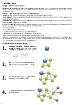
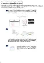
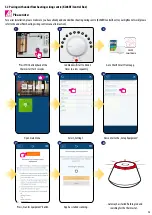
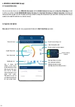
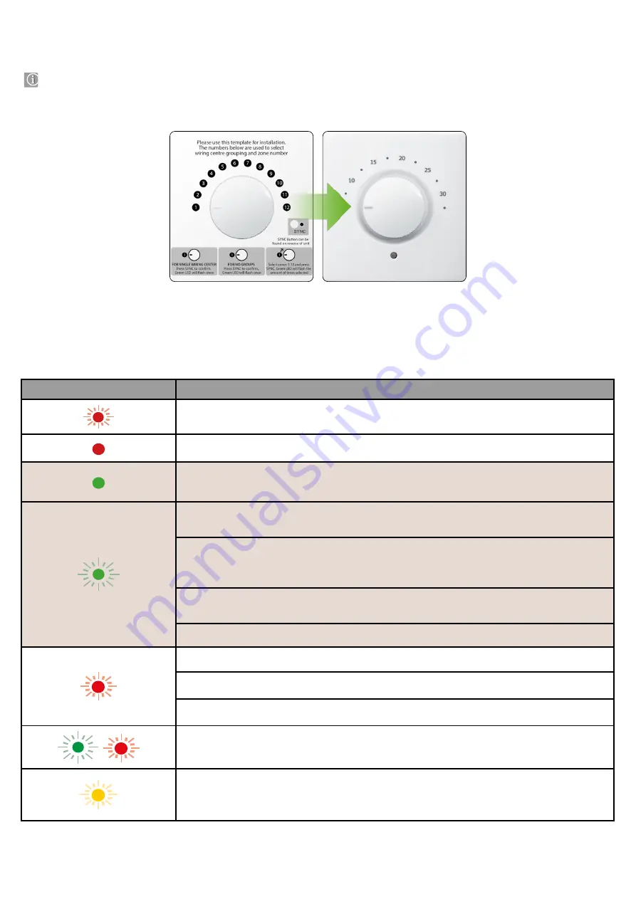
The illustration on the left (pictures below) explains the relationship between the temperature scale and the scale from
instructional sticker. It is useful in the configuration process or in case of a connection loss error. It is recommended to keep the sticker until installation
is complete.
4.1 General informations
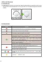
LED diode
Description
Want to join network (Flashing
RED
3 times in a row sequently, then 3.5s off, then again)
Joined the network successfully (constant flash of
RED
diode)
*Pairing process complete (One quick flash of green diode)
Wiring Centre number selection OK (choice of 1 wiring centre - 1 blink of
green
diode as a confirmation, choice of
second wiring centre - 2 blinks of
green
diode as a confirmation, etc.)
Wiring Centre group selection OK (choice of 1 group - 1 blink of
green
diode as a confirmation, choice of second group
- 2 blinks of
green
diode as a confirmation, choice of no grouping - 1 blink of
green
diode as a confirmation, choice of
group 1 - 2 blinks of
green
diode as a confirmation, etc.)
Wiring Centre zone selection OK (choice of 1 zone - 1 blink of
green
diode as a confirmation, choice of second zone - 2
blinks of
green
diode as a confirmation, etc.)
Identify process ON (
green
diode is flashing sequently every 0,75 sec)
Lost connection with CO10RF / KL08RF / UGE600 (
Red
diode is flashing sequently every 0,5 sec)
Low battery (fast 3
red
diode blinks every 10 seconds)
Pairing process failed (
red
diode flash for two seconds)
Error when trying to add two HTR-RF(20) to the same Wiring Centre Zone (
Red
and
green
diodes are blinking
alternately)
- Device reset (
Orange
diode flash for 1 second)
4.2 LED diode indications
4. Before you start (first power up)

