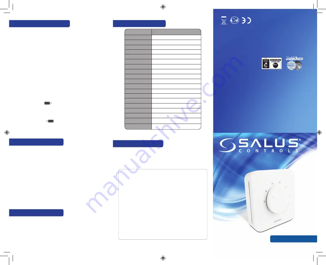
Dial Thermostat
Model: HTR24
INSTALLER MANUAL
SALUS C
ontr
ols plc
SALUS House
Dodw
orth Business P
ark S
outh,
Whinby R
oad,
Dodw
orth, Bar
nsley S75 3SP
, UK.
Sales:
T: +44 (0) 1226 323961
E: sales@salus-tech.com
Technical:
T
: +44 (0) 1226 323961
E: tech@salus-t
ech.com
ww
w.salus-
con
trols
.com
SALUS C
ontr
ols is a member of the Computime Gr
oup
Maintaining a polic
y of continuous produc
t development SAL
US Contr
ols plc reser
ve the r
ight to
change specification, design and mat
erials of pr
oducts list
ed in this brochur
e without prior notice
.
Issue Date: D
ec 2015
00189
For PDF I
nstallation guide please
go to w
ww
.salus-manuals.c
om
8. Technical Specification
Warranty
SALUS Controls warrants that this product (HTR24) will be free from any
defect in materials or workmanship, and shall perform in accordance with
its specification, for a period of five years from the date of installation.
SALUS Controls sole liability for breach of this warranty will be (at its option) to repair
or replace the defective product.
Customer Name: ......................................................................................................................................................
Customer Address: .................................................................................................................................................
............................................................................................................................................................................................
....................................................................................... Post Code: ...........................................................................
Tel No: .................................................................... Email: .......................................................................................
Engineers Company: ..........................................................................................................................................
Tel No: ...................................................................... Email: ....................................................................................
Instalation Date: ....................................................................................................................................................
Engineers Name: ...................................................................................................................................................
Engineers Signature: ...........................................................................................................................................
6. Protection Function
7. Control Patterns
5. Thermostat Functions
NSB (Night SetBack) Function
NSB Mode depends on the NSB wired connection.
0V = NSB OFF
24V= NSB ON
The NSB signal is activated every 1 second. When the signal is received the
setpoint temperature will be set at
±
2°C or
±
4°C.
Heating and Cooling Selection
The Heating/Cooling function is determined by the CO terminal connection.
CO 0V= Heat mode
CO 24V= Cool mode
Cooling Blocked function
Cooling Enabled:
Set the jumper on ON . The thermostat will run in normal cooling mode.
That means that it will open/close the actuators when necessary. The LED will be
BLUE when the cooling function is running.
Cooling Disabled:
Set the jumper on OFF . The actuator will be closed and the LED will
be off.
Heat cut off at high/low temperature:
When room temperature is over 36°C or under 4°C, all heating/cooling outputs
will be turned off.
Short cycle protection:
When Cooling Mode is enabled the minimum interval between Relay ON/OFF
is 3 minutes.
Valve Protection:
Set the jumper on ‘ON’ to disable the function or on ‘OFF’ to enable it. Turn on the
valve for 5 minutes every week to prevent any damage to the valve.
Sensor Malfunction:
If the temperature sensor or temperature sensor compensation is open the LED
will flash BLUE/RED alternatively.
If CO terminal is connected and the Heating Mode is ON, the PWM function
will be activated.
If CO terminal is disconnected and the Cooling Mode is ON the ON/OFF control
output will be activated.
Model:
HTR24
Voltage:
24 V AC, +-10%, 50/60 Hz
Operating Performance:
24 V: 1,8 W
Temperature setback:
Temperature range:
2°C-4°C
5°C- 30°C
Span:
+/- 0,5°C
Calibration
:
Yes, with jumper
Storage temperature:
-20°C to +60°C
Ambient temperature:
0 °C up to 45 °C
Degree of protection
:
IP 30
CE conformity according to:
Class II ( EN60730 )
Housing material
:
PC, V2
Color:
RAL 9010 pure white
Connection:
Screw terminal
Weight
90g net / 135g gross
Puls-wide-modulation:
(PWM)
Yes
Valve protection:
Heating and Cooling:
Cooling blocked:
Dimensions:
Yes
Yes, automatically Change Over on the CO terminal
Yes, with jumper
85mm*85mm*25mm


