background image

69

11. Error codes (error codes description with possible solutions)

Error codes description with possible solutions:

ERROR 

CODE

DISPLAY

 DESCRIPTION

ERROR DESCRIPTION

TROUBLESHOOTING

1.

Err

XX-01

TRV paired with thermostat - TRV 
hardware error.

• Reinstall the TRV head or replace it. If necessary, contact with the 
SALUS Technical Department.

2.

Err

XX-02

Floor is overheated (heating mode).    
/ Floor is overcooled (in cooling 
mode).

• Set the heating medium temperature or change D14 parameter.

• Set the cooling medium temperature or change D16 parameter.

3.

Err

XX-03

Floor sensor is broken.

• If floor sensor is connected to S1/S2 input, check the wiring.
• If floor sensor is not connected, check the D03/D04 parameters settings.

4.

Err

XX-04

Floor sensor is shorted.

• Check floor sensor wire insulation for any damages. Sensor resistance for 
25°C=10kΩ.

5.

Err

XX-05

Thermostat lost contact with the 
CO10RF network coordinator or the 
UGE600 internet gateway.

• Check the coordinator/gateway power supply connection.
• Force identification process from the coordinator/gateway or thermostat.

6.

Err

XX-06

Thermostat lost connection with the 
wiring centre.

Is the wiring centre turned ON and Status Network LED diode solid?
• If yes, send the heating signal from thermostat to the wiring centre 

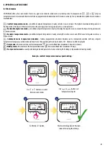
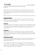
Thermostat constantly monitors the network status, wireless connection status and the operation of connected sensors or paired devices. If it detects any 
failure then following error codes can be displayed alternately with the current room temperature value.

Number of errors

Error code

In Online mode error is also shown in the Smart Home application (with 
detailed description). Exclamation mark informs user about existing errors.


PLEASE NOTE!

Summary of Contents for HTRP-RF(50)

Page 1: ...HTRP RF 50 THERMOSTAT FULL USER MANUAL...

Page 2: ...Plug SPE600 17 5 5 Pairing with Smart Relay SR600 19 5 6 Pairing with RX10RF receiver 21 6 OPERATING in ONLINE MODE by app 23 6 1 General informations 23 6 2 App icons description 23 6 3 Change therm...

Page 3: ...e assigned to another thermostat 55 7 3 Pairing with wirelessTRV radiator head 56 7 4 Pairing with RX10RF receiver 58 8 OPERATING in OFFLINE MODE 59 8 1Work modes 59 8 2 Heat cool mode change KL08RF c...

Page 4: ......
Page 5: ...tions in accordance with standards and regulations in force in the given country and in the EU Never try to connect the device other than as described in the manual Before assembly repair or maintenan...

Page 6: ...RX10RF boiler receiver In combination with Universal Gateway UGE600 this regulator can be controlled over the Internet using SALUS SmartHomeapp Onlinemode WithoutInternetconnection Offlinemode thermos...

Page 7: ...reliability detectionand removal of transmission errors as well as connectivity between established priority devices Security measures include devices authenticated using a unique key pair encrypted c...

Page 8: ...work coordinator toinstallanduseyourdevices UniversalGatewayisNOT CONNECTEDTOTHEINTERNET You can use your devices locally withouttheSmartHomeApp Gateway works in this mode as standard ZigBee coordinat...

Page 9: ...enter installer parameter settings 4 Before you start first power up 4 2 Button description 4 1 LCD icon description 1 Comfort temperature 2 Standard temperature 3 Economic temperature 4 Automatic mo...

Page 10: ...cally power up and start boot sequence Set your thermostat for underfloor heating or radiator heating by or buttons Then confirm by button it will display all icons then thermostat will display the so...

Page 11: ...ure that you have downloaded the Salus Smart Home App from the Google Play or App Store You will need to follow a few easy steps to create an account and then link your thermostat to the Universal Gat...

Page 12: ...ipment Press Scan for equipment button 7 8 App has started scanning 1 2 For easier installation please make sure you have already added underfloor heating wiring centre KL08RF Control Box to your ZigB...

Page 13: ...added before Choose UFHWiring Centre option Thermostat is connected Go to the Smart Home app to configure it 10 Select your thermostat and press Connect equipment button Name your thermostat and go Ne...

Page 14: ...ntrol Box 3 Gateway stop flashing and turn to steady blue color which means pair process has been finished Press Finish button to end the set up process in the app Choose No if you want to set your ow...

Page 15: ...nected Go to the Smart Home app to configure it Press Scan for equipment button 7 8 App has started scanning 2 For easier installation please make sure you have already added wireless TRV radiator hea...

Page 16: ...which means pair process has been finished Press Finish button to end the set up process in the app Choose No if you want to set your own schedule later or Yes if default now Select yourTRV radiator h...

Page 17: ...quipment button 7 8 App has started scanning 2 For easier installation please make sure you have already added Smart Plug SPE600 to your ZigBee network please refer to the Smart Plug SPE600 manual ins...

Page 18: ...color which means pair process has been finished Press Finish button to end the set up process in the app Choose No if you want to set your own schedule later or Yes if default now Select your Smart P...

Page 19: ...quipment button 7 8 App has started scanning 2 For easier installation please make sure you have already added Smart Relay SR600 to your ZigBee network please refer to the Smart Relay SR600 manual ins...

Page 20: ...olor which means pair process has been finished Select your Smart Relay from the list Now choose Smart Relay Select your thermostat and press Connect equipment button Name your thermostat and go Next...

Page 21: ...r equipment button 7 8 App has started scanning 2 For easier installation please make sure you have already added RX10RF receiver to your ZigBee network please refer to the RX10RF receiver manual inst...

Page 22: ...Finish button to end the set up process in the app Choose More to expand the menu Select your thermostat and press Connect equipment button Name your thermostat and go Next Press gear icon 10 11 12 1...

Page 23: ...rowser 6 2 App icons description Menu view of HTRP RF 50 thermostat set as a programmable thermostat in SALUS SmartHome application Thermostat mode selection Thermostat Heat Cool mode indicator Setpoi...

Page 24: ...24 6 3 Change thermostat name pencil icon Name your termostat and confirm it by Save button Click on the pencil icon Select the thermostat in the main app menu 1 2 3 4 Press the thermostat s name...

Page 25: ...sor to left right on your App On your App screen the setpoint temperature is the number displayed in a larger font Select the thermostat in the main app menu 1 2 3 4 Old setpoint value New setpoint va...

Page 26: ...h is animating during cooling When thermostat is calling for heating then flame icon is displayed In the application you will see blue thermostat tile with snowflake icon when cooling mode is on 1 2 W...

Page 27: ...can choose to set the Default schedule that already exist in the App or to modify it according to your preferences The schedule is displayedatthebottomofscreenofyourAppontheselectedthermostat Youcana...

Page 28: ...SUN Daily After days period selection use Add interval option to add your intervals to the schedule Then add a start time and temperature setpoint after all confirm by pressing Add button 4 5 6 TO SE...

Page 29: ...LY You can duplicate the same schedule for other thermostat s Click on the Duplicate schedule option Select thermostat for which you want to duplicate the schedule Now app is saving your choice and af...

Page 30: ...use Default schedule button It will remove all current intervals and it will set default schedule 4 Select thermostat in the main app menu 1 2 3 Scroll down and press pencil icon TO SET DEFAULT SCHEDU...

Page 31: ...s that thermostat is in manual mode 1 2 2 6 6 2Temporary override mode Temporary override mode means manual temperature change during active schedule mode NOTE Temporary override mode will be maintain...

Page 32: ...please followe steps below Note When the thermostat exits frost protection mode previous mode will be restored PLEASE NOTE You can change frost protection mode temperature setpoint from the applicatio...

Page 33: ...lock unlock buttons in your thermostat by application When buttons are locked then also you can see on the thermostat display key icon Click on the padlock icon to lock unlock thermostat buttons 1 2...

Page 34: ...ose If you want to have acces to this function then first you have to add window door sensor OS600 or SW600 please refer to the OS600 or SW600 manual instruction To pair window door sensor OS600 SW600...

Page 35: ...here is no need to heat If you want to have acces to this function then first you have to add SPE600 Smart Plug to the SALUS SmartHome system please refer to the SPE600 manual instruction To pair SPE6...

Page 36: ...to heat If you want to have acces to this function then first you have to add SR600 Smart Relay to the SALUS SmartHome system please refer to the SR600 manual instruction To pair SR600 Smart Relay wi...

Page 37: ...rsal Gateway then we can easily identify which device is paired with which gateway In the Identification mode thermostat s display will start flashing Id information for 10 minutes You can also identi...

Page 38: ...n unpin thermostat from dashboard in Smart Home application please follow steps below 1 2 3 Open main menu in the app Select equipment Select All equipment option Select your HTRP RF 50 thermostat Pre...

Page 39: ...basic settings Select the thermostat in the main app menu Select thermostat s settings 1 2 3 Press thermostat s name Select the hour format for the thermostat Set the frost protection setpoint temper...

Page 40: ...ly for qualified installers or knowledgeable users Scroll down to enter Admin settings Select the thermostat in the main app menu Select thermostat s settings 1 2 3 4 Press thermostat s name All servi...

Page 41: ...s ComfortTemperature set thermostat temperature to 21 C Frost Protection Mode set thermostat to the Frost Mode temperature setpoint can be set in the user settings 5 C by default Holiday Mode set ther...

Page 42: ...example we will create OneTouch rule which activates send me a notification action under temperature is below 10 C condition Please look at the steps below how to set this OneTouch rule Press Add a A...

Page 43: ...ail or SMS notification and enter the message content Confirm by pressing Set button To finish OneTouch rule creation press Save button Choose the condition details for your thermostat In this case se...

Page 44: ...pinned to the dashboard Newly created OneTouch rule tile can be found under OneTouch main menu and on your dashboard To force OneTouch rule activation select it tile 13 17 18 14 15 16 Please note SMS...

Page 45: ...01 03 Floor Sensor Defect means that there is a break in the circuit of the temperature sensor plugged into the S1 S2 contacts of the thermostat or the sensor has been activated and not connected to t...

Page 46: ...y is expressed in decibel units db Compare your value with scale below 50db to 0db very good quality signal 75db to 50db good quality signal 85db to 75db low quality signal 95db to 85db bad quality si...

Page 47: ...teps below NOTE FactoryresetfunctionremovesthermostatfromtheZigBeenetwork Thismeansthatthermostatisnotvisibleanymoreinthe Myequipment list At the very bottom of thermostat s menu choose Remove option...

Page 48: ...e your thermostat from the Zigbee network but you still will be able to see thermostat s tile After factory reset thermostat tile will change to dark grey colour 1 2 3 4 5 Wait few moments to finish f...

Page 49: ...INEmodeusingtheUGE600UniversalGatewayandthenconnectedtotheInternet all devices should be found in the SALUS Smart Home application using Scan for equipment button All devices found in the application...

Page 50: ...zeka nik modu u sterowania pompy w listwie KL08NSB jest beznapi ciowy dlatego pod czaj c pomp CO nale y wykorzysta zewn trzne r d o zasilania pompy N L UWAGA Przeka nik modu u sterowania pompy w listw...

Page 51: ...dtynkowy czarny zasilany 230V VS20WRF Regulator natynkowy bia y zasilany bateryjnie 4xAAA VS20BRF Regulator natynkowy czarny zasilany bateryjnie 4xAAA Powy sze regulatory mog by stosowane wymiennie w...

Page 52: ...lator programowany VS20WRF Maste gr 2 zasilany bateryjnie GRUPA 1 Regulator indywidualnej strefy grzewczej Zasilanie 230V AC Przew d 1 5mm2 Dostarcza instalator V AC Rozdzielacz ogrzewania pod ogowego...

Page 53: ...uttontoconfirm 4 Now thermostat is looking for the signal from the coordinator 3 Set your thermostat for underfloor heating by or buttons Confirm by button In this chapter you will learn how to set HT...

Page 54: ...coordinator When thermostat is succesfully paired main screen will be displayed PLEASE NOTE For easier installation please make sure you have already added Underfloor HeatingWiring Centre Control Box...

Page 55: ...s occupied by other thermostat it will remove it from that zone To do it follow steps below 1 2 3 Press button to confirm zone replacement You can always change the zone using or buttons if you don t...

Page 56: ...r head manual instruction 1 4 7 8 9 2 Set your thermostat for radiators by or buttons Confirm by button 3 OpentheZigBeenetwork OR 5sec 5sec Thermostat is searching forTRVs radiator heads 5 6 Holdthebu...

Page 57: ...57 11 10 12 Close the ZigBee network OR 3 3 5sec 5sec When thermostat is succesfully paired main screen will be displayed TRVhasbeenadded...

Page 58: ...make sure you have already added RX10RF receiver to your ZigBee network please refer to the RX10RF receiver manual instruction 2 3 Now thermostat is looking for the signal from the coordinator 4 Open...

Page 59: ...hermostat works in the cooling system Acting alone works as a manual mode Standardtemperaturemode pre definedsetpointtemperature Usuallysetduringthedaywhenwearearoundthehouse Actingaloneworks as a man...

Page 60: ...ng centre Look at the instructions below When thermostat is calling for cooling then snowflake icon is displayed When thermostat is calling for heating then flame icon is displayed 1 CO terminal of th...

Page 61: ...below There are 4 possible schedule variants Use and buttons to select schedule variant and confirm by button Separate schedule for WORKING DAYS Separate schedule for WEEKENDS One schedule for WHOLEWE...

Page 62: ...grams time periods in the schedule Hold button for 3 seconds to save and exit schedule editing To run the schedule activate thermostat s automatic mode use and buttons to move the frame to the A icon...

Page 63: ...using and buttons Confirm by button Set year using and buttons Confirm by button Set minutes using and buttons Confirm by button Set day using and buttons Confirm by button 3 DATE settings will autom...

Page 64: ...brate thermostat s temperature sensor please follow steps below 1 4 7 6 Set temperature calibration value using and buttons To increase decrease value use and buttons Go to the thermostat calibration...

Page 65: ...displaying 8 3 4 Key lock function To LOCK UNLOCK HTRP RF 50 thermostat keys in OFFLINE MODE you have to press and hold buttons for 3 SECONDS When thermostat is locked you will see key icon on the di...

Page 66: ...button 4 2 Hold buttons for 3 seconds to enter the installer mode dXX Function Parameter Values Description Default Values d00 Temperature unit 0 Celsius C 0 1 Fahrenheit F d01 The method of controlli...

Page 67: ...re that can be set by the user 35 C d13 Cooling temperature limit 5 40 C Minimum heating cooling temperature that can be set by the user 5 C d14 Max floor temperature active in heating mode when d04 1...

Page 68: ...Factory Reset To RESET HTRP RF 50 thermostat to it s factory default settings please follow steps below 1 2 3 4 5 Wait few moments to finish factory reset procedure Use or buttons to choose code 47 Pr...

Page 69: ...orted Check floor sensor wire insulation for any damages Sensor resistance for 25 C 10k 5 Err XX 05 Thermostat lost contact with the CO10RF network coordinator or the UGE600 internet gateway Check the...

Page 70: ...devices are within the network Send the heating signal from thermostat If the top LED diode is flashing perform the pairing procedure according to the RX10RF manual instruction 11 18 Err XX 11 XX 18...

Page 71: ...SALUSTechnical Department 31 Err XX 31 Adaptation error of theTRV head assembled on the radiator valve insert Check assembly of theTRV head on radiator valve insert and reinstall theTRV head Check the...

Page 72: ...rmostat requires no special maintenance Periodically the outer casing can be wiped clean using a dry cloth please DO NOT use solvents polishes detergentsorabrasivecleaners asthesecandamagethethermosta...

Page 73: ...twillbefreefromanydefectinmaterialsorworkmanship andshallperforminaccordancewithitsspecification foraperiodoffiveyearsfromthedateofinstallation SALUSControlssoleliabilityforbreachofthiswarrantywillbe...

Page 74: ...CONTROLS Sp z o o Sp k Rolna 4 43 262 Kobielice Poland www salus controls com SALUS Controls is a member of the Computime Group Maintaining a policy of continuous product development SALUS Controls p...

Reviews: