

Make sure that all the wires are properly connected,
mount top cover and power up the wiring centre
- the
green
„Power” indicator LED will illuminate.
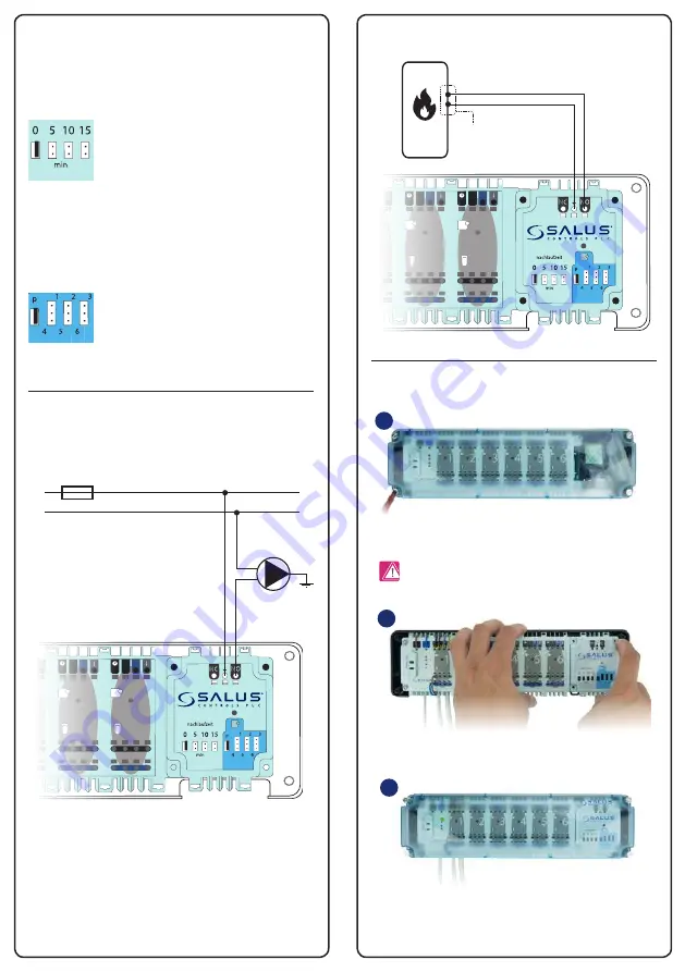
3
Jumpers description
Wiring diagrams
Jumpers 0-15
These are used to set in minutes the delay time (overrun time).
Default setting is „0”.
ON OFF
3
4
Delay
Overrun
ON OFF
1
2
1
2
3
4
5
6
fuse
(T2A)
L N
L N
L N
L N
L N
L N
L
N
CON1
ON OFF
34
D
ela
yO
ver
run
ON OFF
12
12
34
56
fuse
(T2A)
LN
LN
LN
LN
LN
LN
LN
CON1
0-15 values specify the time in minutes. E.g.
when jumper is set to value „0”, COM/NO
output will turn off as soon as the thermostats
stop calling for heat. If jumper will be set to
the value „10”, the module will turn off 10 min
after the thermostats stop calling for heat.
Jumpers P,1,2,3,4,5,6
They are used to select the zone which turns on the module.
Default setting is „P”.
ON OFF
3
4
Delay
Overrun
ON OFF
1
2
1
2
3
4
5
6
fuse
(T2A)
L N
L N
L N
L N
L N
L N
L
N
CON1
ON OFF
34
D
ela
yO
ver
run
ON OFF
12
12
34
56
fuse
(T2A)
LN
LN
LN
LN
LN
LN
LN
CON1
ON OFF
34
D
ela
yO
ver
run
ON OFF
12
12
34
56
fuse
(T2A)
LN
LN
LN
LN
LN
LN
LN
CON1
ON OFF
34
D
ela
yO
ver
run
ON OFF
12
12
34
56
fuse
(T2A)
LN
LN
LN
LN
LN
LN
LN
CON1
P
– all zones start the module
1, 2, 3, 4, 5, 6
– select the specific zone
which turns on the module.
PUMP CONTROL
BOILER CONTROL
INSTALLATION OF THE ADDITIONAL MODULE
ON OFF
3
4
Delay
Overrun
ON OFF
1
2
1
2
3
4
5
6
fuse
(T2A)
L N
L N
L N
L N
L N
L N
L
N
CON1
ON OFF
3
4
Delay
Overrun
ON OFF
1
2
1
2
3
4
5
6
fuse
(T2A)
L N
L N
L N
L N
L N
L N
L
N
CON1
230 V AC
L
L
N
N
PE
max 5 (2) A
ON OFF
3
4
Delay
Overrun
ON OFF
1
2
1
2
3
4
5
6
fuse
(T2A)
L N
L N
L N
L N
L N
L N
L
N
CON1
ON OFF
3
4
Delay
Overrun
ON OFF
1
2
1
2
3
4
5
6
fuse
(T2A)
L N
L N
L N
L N
L N
L N
L
N
CON1
Boiler ON/OFF contacts
(according to the boiler’s
manual)
1
Remove the top cover of the wiring centre.
Note:
Before connecting module, disconnect the main
power from the KL06 wiring centre.
2
Connect the module to the serial connector.


