background image

8

3. Connection description

L

AC 230V

COM

lub

NO

NC

N

L

N

L

AC 230V

N

RT310

RT310

MAX 

3 (1) A

PODŁ

ĄCZENIE  K

OTŁ

*

3V

2 x AA

3V

2 x AA

COM

NO

NC

L

AC 230V

COM

lub

NO

NC

N

L

N

L

AC 230V

N

RT310

RT310

MAX 

3 (1) A

PODŁ

ĄCZENIE  K

OTŁ

*

3V

2 x AA

3V

2 x AA

COM

NO

NC

BOILER C

ONNEC

TION*

or

L, N

 - power supply 230V

NO, COM, NC

 - voltage-free output

- fuse

Legend:

Symbols explanation:

Pump

Valve actuator

Boiler - Boiler connection* 

Boiler’s contacts for ON/OFF 

thermostat (according to the 
boiler’s instructions)

Summary of Contents for RT310

Page 1: ...RT310 HEAT COOL THERMOSTAT FULL USER MANUAL...

Page 2: ...CD icon description 9 4 2 Button description 9 4 3 First power up sequence and configuration 10 5 User settings 11 5 1 Manual mode changing temperature setpoint 11 5 2 Frost protection mode 12 5 3 Sle...

Page 3: ......

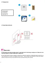
Page 4: ...tions in accordance with standards and regulations in force in the given country and in the EU Never try to connect the device other than as described in the manual Before assembly repair or maintenan...

Page 5: ...perature You won t have to adjust the thermostat further Any adjustment above this setting will waste energy and cost you more money If your heating system is a boiler with radiators there will usuall...

Page 6: ...to sunlight or any extreme conditions like for example draft Because of fire and explosion risk there is not allowed to use thermostat in atmosphere of explosive gases and flammable liquids eg coal d...

Page 7: ...ing and a German and UK wall box to mount the thermostat directly into the wall The standard wall box has a diameter max 60mm and depth from 41 46 mm The cable entry on the backplate must allow a cabl...

Page 8: ...NO NC COM lub NO NC N L L AC 230V N 0 RT310 MAX 3 1 A POD CZENIE KOT A 3V 2 x AA COM NO NC BOILER CONNECTION or L N power supply 230V NO COM NC voltage free output fuse Legend Symbols explanation Pum...

Page 9: ...ndication 3 RF signal indicator only in RT310RF 4 Low battery status 5 Temperature unit 6 Room setpoint temperature PLEASE NOTE The LCD screen can be activated by using any button 1 TurnontheLCDbackli...

Page 10: ...stat will display following sequence 1 2 4 3 Remove the protection foil and insert 2xAA batteries by removing front cover then thermostat will display the software version After that thermostat will a...

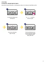
Page 11: ...user To set temperature setpoint follow steps below 1 2 4 3 First thermostat is displaying actual room temperature Now wait 2 seconds timeout to approve the changes Thermostat will display main scree...

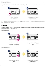
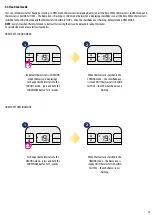
Page 12: ...again To activate deactivate sleep mode follow steps below TO DEACTIVATE SLEEP MODE TO ACTIVATE SLEEP MODE Press button to turn ON OFF frost protection Press and hold buttons simultanously to turn ON...

Page 13: ...hen it can be delayed for about 3 minutes To set selected mode please follow steps below HOWTO SET COOLING MODE HOWTO SET HEATING MODE By default thermostat is in HEATING mode flame icon is displaying...

Page 14: ...s below the lower limit as shown in the images Battery voltage is checked every minute When the battery voltage drops to a certain level the Low Battery warning indicator appears The thermostat functi...

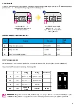
Page 15: ...and a higher comfort level 9 CPH CPH means cycles per hour and it relates to the frequency of the measurement cycles performed by thermostat DETAILEDTABLEWITH ALL INSTALLER PARAMETERS Press and hold s...

Page 16: ...16 7 Reset function To RESET RT310 thermostat please follow steps below RESET Press the RESET button once You can use a paper clip Your thermostat will be reset and will start up automatically 1...

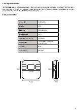
Page 17: ...mm 96 x 96 x 27 TheRT310thermostatrequiresnospecialmaintenance Periodically theoutercasingcanbewipedcleanusingadrycloth pleaseDONOTusesolvents polishes detergents or abrasive cleaners as these can da...

Page 18: ...or replacing the defective product This product includes software that matches the distributor s identification at the time of sale The manufacturer distributor provides a guarantee covering all func...

Page 19: ......

Page 20: ...LS Sp z o o Sp k Rolna 4 43 262 Kobielice Poland www salus controls com SALUS Controls is a member of the Computime Group Maintaining a policy of continuous product development SALUS Controls plc rese...

Reviews: